
Loose Leaf for Engineering Circuit Analysis Format: Loose-leaf
9th Edition
ISBN: 9781259989452
Author: Hayt
Publisher: Mcgraw Hill Publishers
expand_more
expand_more
format_list_bulleted
Videos
Textbook Question
Chapter 3, Problem 4E
For the circuit of Fig. 3.47:
(a) Count the number of circuit elements.
(b) If we move from B to C to D, have we formed a path? Have we formed a loop?
(c) If we move from E to D to C to B, have we formed a path? Have we formed a loop?
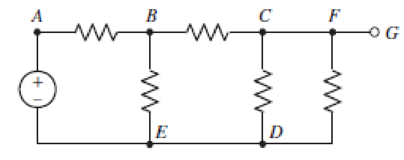
■ FIGURE 3.47
Expert Solution & Answer
Want to see the full answer?
Check out a sample textbook solution
Students have asked these similar questions
Directions: The illustration below shows the components of a simple circuit diagram. Choose
from the choices on the left the best term or description that will match each component and
its function. Write your answer on the prescribed box.
• Battery
Component:
Function:
Load
Switch
• Wire
Converts electrical
Component:
Component:
energy into heat,
light, or mechanical
Function:
Function:
energy
• Completes or breaks
circuit by allowing or
stopping current
from flowing
• Provides a route for
Component
Function:
the current to flow
through
• Supplies electrical
energy that causes
current flow
Q3- Compute the following equation by using a) Single loop b) No-loop
19
Mn] = EMk]x[n +k]
%3D
Activity #3: How A and V placed in a circuit?
Directions: Complete the sentence by supplying the correct term in the space
provided.
The voltmeter (V) is connected in parallel with the device. The ammeter (A)
is connected in series in the circuit so that all current passing through the circuit
must pass through and be measured by the ammeter.
OF PASIG
volimeter
V
Battery
A
Resiste nce
http://armymedical.tpub.com/md0950/Placement-of-voltmeter-and-ammeter-in-circuit
NOISIAI
Chapter 3 Solutions
Loose Leaf for Engineering Circuit Analysis Format: Loose-leaf
Ch. 3.2 - 3.1 (a) Count the number of branches and nodes in...Ch. 3.3 - Determine ix and vx in the circuit of Fig. 3.7....Ch. 3.3 - For the circuit of Fig. 3.9, if vR1=1V, determine...Ch. 3.3 - Determine vx in the circuit of Fig. 3.11.Ch. 3.4 - In the circuit of Fig. 3.12b, vs1 = 120 V, vs2 =...Ch. 3.4 - 3.6 In the circuit of Fig. 3.14, find the power...Ch. 3.5 - Determine v in the circuit of Fig. 3.16.Ch. 3.5 - For the single-node-pair circuit of Fig. 3.18,...Ch. 3.6 - Determine the current i in the circuit of Fig....Ch. 3.6 - Determine the voltage v in the circuit of Fig....
Ch. 3.6 - Determine whether the circuit of Fig. 3.25...Ch. 3.7 - 3.12 Determine a single-value equivalent...Ch. 3.7 - 3.13 Determine i in the circuit of Fig. 3.29....Ch. 3.7 - Determine v in the circuit of Fig. 3.31 by first...Ch. 3.7 - 3.15 For the circuit of Fig. 3.33, calculate the...Ch. 3.8 - 3.16 Use voltage division to determine vx in the...Ch. 3.8 - In the circuit of Fig. 3.40, use resistance...Ch. 3 - Referring to the circuit depicted in Fig. 3.45,...Ch. 3 - Referring to the circuit depicted in Fig. 3.46,...Ch. 3 - For the circuit of Fig. 3.47: (a) Count the number...Ch. 3 - For the circuit of Fig. 3.47: (a) Count the number...Ch. 3 - Refer to the circuit of Fig. 3.48, and answer the...Ch. 3 - A local restaurant has a neon sign constructed...Ch. 3 - Referring to the single-node diagram of Fig. 3.50,...Ch. 3 - Determine the current labeled I in each of the...Ch. 3 - In the circuit shown in Fig. 3.52, the resistor...Ch. 3 - The circuit of Fig. 3.53 represents a system...Ch. 3 - In the circuit depicted in Fig. 3.54, ix is...Ch. 3 - For the circuit of Fig. 3.55 (which employs a...Ch. 3 - Determine the current labeled I3 in the circuit of...Ch. 3 - Study the circuit depicted in Fig. 3.57, and...Ch. 3 - Prob. 15ECh. 3 - For the circuit of Fig. 3.58: (a) Determine the...Ch. 3 - For each of the circuits in Fig. 3.59, determine...Ch. 3 - Use KVL to obtain a numerical value for the...Ch. 3 - Prob. 19ECh. 3 - In the circuit of Fig. 3.55, calculate the voltage...Ch. 3 - Determine the value of vx as labeled in the...Ch. 3 - Consider the simple circuit shown in Fig. 3.63....Ch. 3 - (a) Determine a numerical value for each current...Ch. 3 - The circuit shown in Fig. 3.65 includes a device...Ch. 3 - The circuit of Fig. 3.12b is constructed with the...Ch. 3 - Obtain a numerical value for the power absorbed by...Ch. 3 - Compute the power absorbed by each element of the...Ch. 3 - Compute the power absorbed by each element in the...Ch. 3 - Kirchhoffs laws apply whether or not Ohms law...Ch. 3 - Referring to the circuit of Fig. 3.70, (a)...Ch. 3 - Determine a value for the voltage v as labeled in...Ch. 3 - Referring to the circuit depicted in Fig. 3.72,...Ch. 3 - Determine the voltage v as labeled in Fig. 3.73,...Ch. 3 - Although drawn so that it may not appear obvious...Ch. 3 - Determine the numerical value for veq in Fig....Ch. 3 - Determine the numerical value for ieq in Fig....Ch. 3 - For the circuit presented in Fig. 3.76. determine...Ch. 3 - Determine the value of v1 required to obtain a...Ch. 3 - (a) For the circuit of Fig. 3.78, determine the...Ch. 3 - What value of IS in the circuit of Fig. 3.79 will...Ch. 3 - (a) Determine the values for IX and VY in the...Ch. 3 - Determine the equivalent resistance of each of the...Ch. 3 - For each network depicted in Fig. 3.82, determine...Ch. 3 - (a) Simplify the circuit of Fig. 3.83 as much as...Ch. 3 - (a) Simplify the circuit of Fig. 3.84, using...Ch. 3 - Making appropriate use of resistor combination...Ch. 3 - Calculate the voltage labeled vx in the circuit of...Ch. 3 - Determine the power absorbed by the 15 resistor...Ch. 3 - Calculate the equivalent resistance Req of the...Ch. 3 - Show how to combine four 100 resistors to obtain...Ch. 3 - Prob. 51ECh. 3 - Prob. 52ECh. 3 - Prob. 53ECh. 3 - Prob. 54ECh. 3 - Prob. 55ECh. 3 - Prob. 56ECh. 3 - Prob. 57ECh. 3 - Prob. 58ECh. 3 - Prob. 59ECh. 3 - Prob. 60ECh. 3 - With regard to the circuit shown in Fig. 3.98,...Ch. 3 - Delete the leftmost 10 resistor in the circuit of...Ch. 3 - Consider the seven-element circuit depicted in...
Knowledge Booster


Learn more about
Need a deep-dive on the concept behind this application? Look no further. Learn more about this topic, electrical-engineering and related others by exploring similar questions and additional content below.Similar questions
- can you please solve step by step(showing everything clearly) I will give upvote :) Thanksarrow_forwardReferring to the network in the Figure 1 (a) Apply node analysis to all unknown nodes in Figure 1. Based on this analysis, specify all the equations that you have obtained. (b) Based on the equations obtained above, is there any possible solution? State the reason for your answer. If the solution is impossible, suggest a simple addition orchange to the network above, and prove that your suggestion is valid.arrow_forwardnodes paths loops meshes branchesarrow_forward
- 1. Calculate the resistance that RL must have, so that the maximum power transfer occurs (obtaining 〖RL〗 _max).2. Calculate the largest power that can be consumed in RL3. What is the value of RL, such that the power consumed is 1/3 of the maximum and the voltage between its terminals is the lowest.arrow_forwardHello sir, My Name is S Vishnu Vardhan studying BTECH 4th year EEE Sir as you can see in the diagram below when the voltage is zero current is maximum at the beginning, ie at the time when the circuit is turned on, but we studied in earlier classes that there must exist a voltage to make current flow, How come a zero voltage can make current maximum?. NOTE- Earlier many people convinced me that at the beginning max voltage change lead a max current but still we can see at absolute zero voltage current is maximum(why?). Vmax- V Imax: - 360° ,90° Ov 90° 180° ot V 4f I V4f Charge Discharge Charge Dischargearrow_forward3.) Show complete solutionsarrow_forward
- Facts: A schematic diagram is a fundamental two-dimensional circuit representation showing the functionality and connectivity between different electrical components. Question: In your own opinion, give at least 5 factors to consider in making a good schematic diagram?arrow_forward2. Give some examples where Potentiometer are being used in our daily lives C. MATERIALS/INSTRUMENTS 1x Breadboard • 1x Arduino Uno R3 • 1x USB AB Cable/Printer Cable • 1x LED • 1x 3300 Resistor . 1x 10k Potentiometer • Jumper Wires D. PROCEDURES The circuit of this interactive potentiometer is prototyped on a breadboard. LED are interfaced with the Arduino and together with the potentiometer. 1. Mount the resistor of LED and Potentiometer on the breadboard. Connect one end of the 330 ohms resistor to a digital pin on the Arduino board using a jumper wire. 2. Mount the LED on the breadboard. Connect the anode (+) pin of the LED to the available pin on the resistor. We can determine the anode on the LED in two ways. Usually, the longer pin is the anode. Another way is to look for the flat edge on the outer casing of the LED. The pin next to the flat edge is the cathode (-). Microprocessor Laboratory 5 Name: Section: Class number: Date: Schedule: 3. Connect the LED cathode (-) to the…arrow_forwardsubject:Circuitsshow your solution pleasearrow_forward
- LMH_chapter3-part 1-homework [Protected View] PowerPoint ĐĂNG PHẠM HỒNG 困 O X File Home Insert Design Transitions Animations Slide Show Review View Help Tell me what you want to do & Share PROTECTED VIEW Be careful-files from the Internet can contain viruses. Unless you need to edit, it's safer to stay in Protected View. Enable Editing 1 HW14 Chapter III AC Circuit Analysis Homework part 1 Reading: Chapter 05 Textbook: Fundamental of Electric 5.7 The op amp in Fig. 5.46 has R; = 100 kN, R, = 100 0, A = 100,000. Find the differential voltage va and the output voltage v,. Circuits Textbook HW14 5.7 The op amp in Fig 5.46 has R, - 100 k, R, - 100 2, 4 - 100,000. Find he dillerential voltage e, and the output voltage e. 10 100 k I mv E) HW15 10 k2 100 k2 5.10 Find the gain /v, of the circait in Fig. 5.49. ww 37 ko 20 k2 1 mV 10 ka 4 HW16 5.13 Find u, andi, in the circuit of Fig. 5.52. E90 ka 100 ka ww 10 ka 50 k2 Slide 2 of 14 English (United States) Comments 90% 11:49 AM O Type here to…arrow_forward2. In the figure shown below, is=10 A and R3 = 1000 Q. The current i, should be divided between R1 and R2 such that iz=10 mA. Calculate the ratio between R1 and R2 required to create this outcome. a) R2=1000×R1 Please write out your detailed solutions for each question. b) R12999×R2 c) R2=999×R1 d) None of the above. R3 + is R1 i, v R2.arrow_forwardnote: - list down the given and problem to solve. - used formula with derivation - complete solution with unit analysis. - schematic diagram - interpretationarrow_forward
arrow_back_ios
SEE MORE QUESTIONS
arrow_forward_ios
Recommended textbooks for you
 Introductory Circuit Analysis (13th Edition)Electrical EngineeringISBN:9780133923605Author:Robert L. BoylestadPublisher:PEARSON
 Delmar's Standard Textbook Of ElectricityElectrical EngineeringISBN:9781337900348Author:Stephen L. HermanPublisher:Cengage Learning
 Programmable Logic ControllersElectrical EngineeringISBN:9780073373843Author:Frank D. PetruzellaPublisher:McGraw-Hill Education
 Fundamentals of Electric CircuitsElectrical EngineeringISBN:9780078028229Author:Charles K Alexander, Matthew SadikuPublisher:McGraw-Hill Education
 Electric Circuits. (11th Edition)Electrical EngineeringISBN:9780134746968Author:James W. Nilsson, Susan RiedelPublisher:PEARSON
 Engineering ElectromagneticsElectrical EngineeringISBN:9780078028151Author:Hayt, William H. (william Hart), Jr, BUCK, John A.Publisher:Mcgraw-hill Education,
Introductory Circuit Analysis (13th Edition)
Electrical Engineering
ISBN:9780133923605
Author:Robert L. Boylestad
Publisher:PEARSON
Delmar's Standard Textbook Of Electricity
Electrical Engineering
ISBN:9781337900348
Author:Stephen L. Herman
Publisher:Cengage Learning
Programmable Logic Controllers
Electrical Engineering
ISBN:9780073373843
Author:Frank D. Petruzella
Publisher:McGraw-Hill Education
Fundamentals of Electric Circuits
Electrical Engineering
ISBN:9780078028229
Author:Charles K Alexander, Matthew Sadiku
Publisher:McGraw-Hill Education
Electric Circuits. (11th Edition)
Electrical Engineering
ISBN:9780134746968
Author:James W. Nilsson, Susan Riedel
Publisher:PEARSON
Engineering Electromagnetics
Electrical Engineering
ISBN:9780078028151
Author:Hayt, William H. (william Hart), Jr, BUCK, John A.
Publisher:Mcgraw-hill Education,
[1.2] 8086 Microprocessor Architecture; Author: ThinkX Academy;https://www.youtube.com/watch?v=XX9rDGTBGgQ;License: Standard Youtube License