
Loose Leaf for Engineering Circuit Analysis Format: Loose-leaf
9th Edition
ISBN: 9781259989452
Author: Hayt
Publisher: Mcgraw Hill Publishers
expand_more
expand_more
format_list_bulleted
Videos
Textbook Question
Chapter 3, Problem 43E
For each network depicted in Fig. 3.82, determine a single equivalent resistance if R = (a) 2 Ω; (b) 4 Ω; (c) 0 Ω.
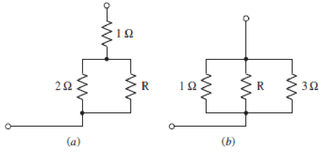
■ FIGURE 3.82
Expert Solution & Answer
Want to see the full answer?
Check out a sample textbook solution
Students have asked these similar questions
2. Sketch the output waveforms expected when a 100 Hz, 5 Vp sine wave is applied
to each of the circuits in Fig. 3.51. Specify important voltage levels and time
scales. The input is on the left and the output is on the right.
3.32. While constructing a full-wave rectifier, a
student mistakenly has swapped the termi-
nals of D3 as depicted in Fig. 3.82. Explain
what happens.
Vin
D2 Vout
W
RL
Figure 3.82
DA
D3
D₁
Q3//
Find i.(1) for t> 0 in the circuit in Figure 3.
3 k2
i (1) 6 kN
9 k2
6V
200 µF
24 V
Figure 3
Chapter 3 Solutions
Loose Leaf for Engineering Circuit Analysis Format: Loose-leaf
Ch. 3.2 - 3.1 (a) Count the number of branches and nodes in...Ch. 3.3 - Determine ix and vx in the circuit of Fig. 3.7....Ch. 3.3 - For the circuit of Fig. 3.9, if vR1=1V, determine...Ch. 3.3 - Determine vx in the circuit of Fig. 3.11.Ch. 3.4 - In the circuit of Fig. 3.12b, vs1 = 120 V, vs2 =...Ch. 3.4 - 3.6 In the circuit of Fig. 3.14, find the power...Ch. 3.5 - Determine v in the circuit of Fig. 3.16.Ch. 3.5 - For the single-node-pair circuit of Fig. 3.18,...Ch. 3.6 - Determine the current i in the circuit of Fig....Ch. 3.6 - Determine the voltage v in the circuit of Fig....
Ch. 3.6 - Determine whether the circuit of Fig. 3.25...Ch. 3.7 - 3.12 Determine a single-value equivalent...Ch. 3.7 - 3.13 Determine i in the circuit of Fig. 3.29....Ch. 3.7 - Determine v in the circuit of Fig. 3.31 by first...Ch. 3.7 - 3.15 For the circuit of Fig. 3.33, calculate the...Ch. 3.8 - 3.16 Use voltage division to determine vx in the...Ch. 3.8 - In the circuit of Fig. 3.40, use resistance...Ch. 3 - Referring to the circuit depicted in Fig. 3.45,...Ch. 3 - Referring to the circuit depicted in Fig. 3.46,...Ch. 3 - For the circuit of Fig. 3.47: (a) Count the number...Ch. 3 - For the circuit of Fig. 3.47: (a) Count the number...Ch. 3 - Refer to the circuit of Fig. 3.48, and answer the...Ch. 3 - A local restaurant has a neon sign constructed...Ch. 3 - Referring to the single-node diagram of Fig. 3.50,...Ch. 3 - Determine the current labeled I in each of the...Ch. 3 - In the circuit shown in Fig. 3.52, the resistor...Ch. 3 - The circuit of Fig. 3.53 represents a system...Ch. 3 - In the circuit depicted in Fig. 3.54, ix is...Ch. 3 - For the circuit of Fig. 3.55 (which employs a...Ch. 3 - Determine the current labeled I3 in the circuit of...Ch. 3 - Study the circuit depicted in Fig. 3.57, and...Ch. 3 - Prob. 15ECh. 3 - For the circuit of Fig. 3.58: (a) Determine the...Ch. 3 - For each of the circuits in Fig. 3.59, determine...Ch. 3 - Use KVL to obtain a numerical value for the...Ch. 3 - Prob. 19ECh. 3 - In the circuit of Fig. 3.55, calculate the voltage...Ch. 3 - Determine the value of vx as labeled in the...Ch. 3 - Consider the simple circuit shown in Fig. 3.63....Ch. 3 - (a) Determine a numerical value for each current...Ch. 3 - The circuit shown in Fig. 3.65 includes a device...Ch. 3 - The circuit of Fig. 3.12b is constructed with the...Ch. 3 - Obtain a numerical value for the power absorbed by...Ch. 3 - Compute the power absorbed by each element of the...Ch. 3 - Compute the power absorbed by each element in the...Ch. 3 - Kirchhoffs laws apply whether or not Ohms law...Ch. 3 - Referring to the circuit of Fig. 3.70, (a)...Ch. 3 - Determine a value for the voltage v as labeled in...Ch. 3 - Referring to the circuit depicted in Fig. 3.72,...Ch. 3 - Determine the voltage v as labeled in Fig. 3.73,...Ch. 3 - Although drawn so that it may not appear obvious...Ch. 3 - Determine the numerical value for veq in Fig....Ch. 3 - Determine the numerical value for ieq in Fig....Ch. 3 - For the circuit presented in Fig. 3.76. determine...Ch. 3 - Determine the value of v1 required to obtain a...Ch. 3 - (a) For the circuit of Fig. 3.78, determine the...Ch. 3 - What value of IS in the circuit of Fig. 3.79 will...Ch. 3 - (a) Determine the values for IX and VY in the...Ch. 3 - Determine the equivalent resistance of each of the...Ch. 3 - For each network depicted in Fig. 3.82, determine...Ch. 3 - (a) Simplify the circuit of Fig. 3.83 as much as...Ch. 3 - (a) Simplify the circuit of Fig. 3.84, using...Ch. 3 - Making appropriate use of resistor combination...Ch. 3 - Calculate the voltage labeled vx in the circuit of...Ch. 3 - Determine the power absorbed by the 15 resistor...Ch. 3 - Calculate the equivalent resistance Req of the...Ch. 3 - Show how to combine four 100 resistors to obtain...Ch. 3 - Prob. 51ECh. 3 - Prob. 52ECh. 3 - Prob. 53ECh. 3 - Prob. 54ECh. 3 - Prob. 55ECh. 3 - Prob. 56ECh. 3 - Prob. 57ECh. 3 - Prob. 58ECh. 3 - Prob. 59ECh. 3 - Prob. 60ECh. 3 - With regard to the circuit shown in Fig. 3.98,...Ch. 3 - Delete the leftmost 10 resistor in the circuit of...Ch. 3 - Consider the seven-element circuit depicted in...
Additional Engineering Textbook Solutions
Find more solutions based on key concepts
Write the nodal equations for the network of Fig. 8.137 using the general approach. Find the nodal voltages usi...
Introductory Circuit Analysis (13th Edition)
Identify the type of input and output configuration for each diff-amp in Figure 18-35.
Electronics Fundamentals: Circuits, Devices & Applications
For the “tank” circuit in Fig. 14.79, find the resonant frequency.
Figure 14.79
For Probs. 14.39, 14.71, and 1...
Fundamentals of Electric Circuits
When travelers from the USA and Canada visit Europe, they encounter a different power distribution system. Wall...
Electric machinery fundamentals
Design an ideal inverting op-amp circuit such that the voltage gain is Av=25 . The maximum current in any resis...
Microelectronics: Circuit Analysis and Design
Electric power systems provide energy in a variety of commercial and industrial settings. Make a list of system...
Principles and Applications of Electrical Engineering
Knowledge Booster


Learn more about
Need a deep-dive on the concept behind this application? Look no further. Learn more about this topic, electrical-engineering and related others by exploring similar questions and additional content below.Similar questions
- Q3) A) A moving-coil instrument gives a f.s.d. when the current is 200 µA and its resistance is 200 2. Calculate the value of shunt resistance to be connected in parallel with the meter to enable it to be used as an ammeter for measuring currents up to 500 mA.arrow_forwardEmploy superposition to determine the individual contribution from each independent source to the voltage v as labeled in the circuit shown in Figure 3. 10 6 A 4 A 3 0 0.4i| Figure 3arrow_forwarda) Apply nodal analysis to solve for Vx in the circuit of figure Ba. Copyright © The McGraw-Hill Companies, Inc. Permission required for reproduction or display 2 A (4) 10 Ω V 20 Ω 0.2Vx Figure Ba b) A battery has a short-circuit current of 20-A and an open-circuit voltage of 12-V. If the battery is connected to an electric bulb of resistance 2-0, calculate the power dissipated by the bulb. +arrow_forward
- R3 = 1 N a R 2Ω R2 2 3N E2 6 V E 10 V E, +8 V Find the current with the following conditions: If student code is down with odd numbers, find current 1. If student code is down with even numbers, find current 12 (current and symbols supplied are not required accordingly).arrow_forwardQuestion 3 Figure Q3.0 presents an electric circuit. Model the circuit in the Simscape environment for G(s) = Vi(s) Vo(s) 292 292 4 H F не 492 Figure Q3.0 6 H 0000 892 www vo(t)arrow_forwardQuestion 11 In the circuit depicted in Fig. 3.53, ix is determined to be 1.5 A, and the 9 V source supplies a current of 7.6 A (that is, a current of 7.6 A leaves the positive reference terminal of the 9 V source). Determine the value of resistor R₁. -1.6 A +++* 9 V(+ RA 6Ω FIGURE 3.53 www 5Ω Vxarrow_forward
- A circuit consists of three capacitors and one battery as shown. Calculate the volts associated with the 105 µF capacitor, C2. V = 16 V, C= 125 µF, C2=105 µF, C3=70 µF %3D Numeric entry only. For example: 22.1 C1 C2 ZZZZZA ZZZZZA ZZZ/7 C3arrow_forwardA, R3=20 R3=60 A3 R,=42 R=20 14V A2 R=42 (As A6, R2=30 A, R,=32 R,=30 w Using the given circuit, calculate: 1) Equivalent resistorarrow_forwardb) ii) Find the Thevenin equivalent circuit at terminal a-b; 30 Ω ww 10V 20 Ω Ω 50 Ω 50 Ω 8 Ω Figure Q3a εξα Find the voltage V, in the circuit of Figure Q3b by using Superposition Theorem. 100 Ω www να 75 Ω ww Μ |10V 4Ω 14 (1 Figure Q3b a b 200 Ωarrow_forward
- Show that the two systems shown in Figure (1) are equivalent. Depend on your study, what is this system called? R(s) R(s) 1 1+7s+TT (a) (تارت | (b) K₂(1 +Ts) K₂(1+¹+T) T₁ Figure (1) G₂ (s) C(s) C(s)arrow_forward(b) (c) FIGURE 3.22 (Continued on next page) CHAPTER 3 VOLTAGE AND CURRENT LAWS PRACTICE 3.10 Determine the voltage v in the circuit of Fig. 3.23 after first replacing the three sources with a single equivalent source. 5 A 10 Ω 1 A 10 Ω> 6Α I FIGURE 3.23 Ans: 50 V. To conclude the discussion of parallel and series source combinations, we should consider the parallel combination of two voltage sources and the series combination of two current sources. For instance, what is the equiva- lent of a 5 V source in parallel with a 10 V source? By the definition of a voltage source, the voltage across the source cannot change; by Kirchhoff's voltage law, then, 5 equals 10 and we have hypothesized a physical impos- sibility. Thus, ideal voltage sources in parallel are permissible only when each has the same terminal voltage at every instant. In a similar way, two current sources may not be placed in series unless each has the same cur- rent, including sign, for every instant of time. XAMPLE 3.1O…arrow_forwardSolve the total resistance, total current, individual currents, and individual voltages of the following dc circuits. R;=20 R= 10 R2 =6 2 12 V R3= 40 R=40 ww w- R;= 32 Re= 1 Ωarrow_forward
arrow_back_ios
SEE MORE QUESTIONS
arrow_forward_ios
Recommended textbooks for you
 Introductory Circuit Analysis (13th Edition)Electrical EngineeringISBN:9780133923605Author:Robert L. BoylestadPublisher:PEARSON
 Delmar's Standard Textbook Of ElectricityElectrical EngineeringISBN:9781337900348Author:Stephen L. HermanPublisher:Cengage Learning
 Programmable Logic ControllersElectrical EngineeringISBN:9780073373843Author:Frank D. PetruzellaPublisher:McGraw-Hill Education
 Fundamentals of Electric CircuitsElectrical EngineeringISBN:9780078028229Author:Charles K Alexander, Matthew SadikuPublisher:McGraw-Hill Education
 Electric Circuits. (11th Edition)Electrical EngineeringISBN:9780134746968Author:James W. Nilsson, Susan RiedelPublisher:PEARSON
 Engineering ElectromagneticsElectrical EngineeringISBN:9780078028151Author:Hayt, William H. (william Hart), Jr, BUCK, John A.Publisher:Mcgraw-hill Education,
Introductory Circuit Analysis (13th Edition)
Electrical Engineering
ISBN:9780133923605
Author:Robert L. Boylestad
Publisher:PEARSON
Delmar's Standard Textbook Of Electricity
Electrical Engineering
ISBN:9781337900348
Author:Stephen L. Herman
Publisher:Cengage Learning
Programmable Logic Controllers
Electrical Engineering
ISBN:9780073373843
Author:Frank D. Petruzella
Publisher:McGraw-Hill Education
Fundamentals of Electric Circuits
Electrical Engineering
ISBN:9780078028229
Author:Charles K Alexander, Matthew Sadiku
Publisher:McGraw-Hill Education
Electric Circuits. (11th Edition)
Electrical Engineering
ISBN:9780134746968
Author:James W. Nilsson, Susan Riedel
Publisher:PEARSON
Engineering Electromagnetics
Electrical Engineering
ISBN:9780078028151
Author:Hayt, William H. (william Hart), Jr, BUCK, John A.
Publisher:Mcgraw-hill Education,
[1.2] 8086 Microprocessor Architecture; Author: ThinkX Academy;https://www.youtube.com/watch?v=XX9rDGTBGgQ;License: Standard Youtube License