
Loose Leaf for Engineering Circuit Analysis Format: Loose-leaf
9th Edition
ISBN: 9781259989452
Author: Hayt
Publisher: Mcgraw Hill Publishers
expand_more
expand_more
format_list_bulleted
Videos
Textbook Question
Chapter 3, Problem 11E
In the circuit depicted in Fig. 3.54, ix is determined to be 1.5 A, and the 9 V source supplies a current of 7.6 A (that is, a current of 7.6 A leaves the positive reference terminal of the 9 V source). Determine the value of resistor RA.
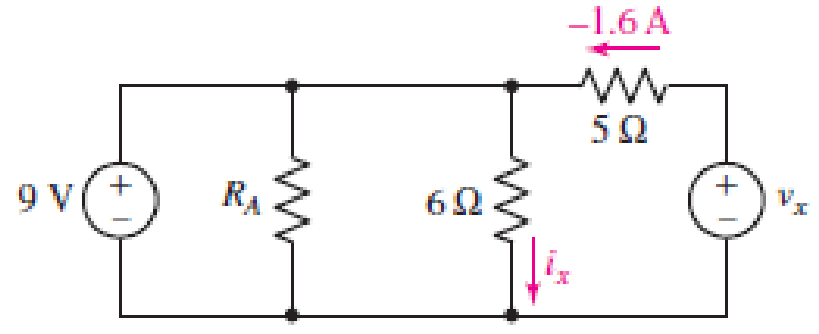
FIGURE 3.54
Expert Solution & Answer
Want to see the full answer?
Check out a sample textbook solution
Students have asked these similar questions
A certain solar cell type has an output capability of 0.3 A at 0.4 V. A series/parallel solar array has been designed
of such cells with 183 parallel strings and each string has 261 cells in series. Calculate Voltage capability of array.
Answer:
3.32. While constructing a full-wave rectifier, a
student mistakenly has swapped the termi-
nals of D3 as depicted in Fig. 3.82. Explain
what happens.
Vin
D2 Vout
W
RL
Figure 3.82
DA
D3
D₁
Determine the current I using the approximate/practical equivalent model for the sketch circuit
Chapter 3 Solutions
Loose Leaf for Engineering Circuit Analysis Format: Loose-leaf
Ch. 3.2 - 3.1 (a) Count the number of branches and nodes in...Ch. 3.3 - Determine ix and vx in the circuit of Fig. 3.7....Ch. 3.3 - For the circuit of Fig. 3.9, if vR1=1V, determine...Ch. 3.3 - Determine vx in the circuit of Fig. 3.11.Ch. 3.4 - In the circuit of Fig. 3.12b, vs1 = 120 V, vs2 =...Ch. 3.4 - 3.6 In the circuit of Fig. 3.14, find the power...Ch. 3.5 - Determine v in the circuit of Fig. 3.16.Ch. 3.5 - For the single-node-pair circuit of Fig. 3.18,...Ch. 3.6 - Determine the current i in the circuit of Fig....Ch. 3.6 - Determine the voltage v in the circuit of Fig....
Ch. 3.6 - Determine whether the circuit of Fig. 3.25...Ch. 3.7 - 3.12 Determine a single-value equivalent...Ch. 3.7 - 3.13 Determine i in the circuit of Fig. 3.29....Ch. 3.7 - Determine v in the circuit of Fig. 3.31 by first...Ch. 3.7 - 3.15 For the circuit of Fig. 3.33, calculate the...Ch. 3.8 - 3.16 Use voltage division to determine vx in the...Ch. 3.8 - In the circuit of Fig. 3.40, use resistance...Ch. 3 - Referring to the circuit depicted in Fig. 3.45,...Ch. 3 - Referring to the circuit depicted in Fig. 3.46,...Ch. 3 - For the circuit of Fig. 3.47: (a) Count the number...Ch. 3 - For the circuit of Fig. 3.47: (a) Count the number...Ch. 3 - Refer to the circuit of Fig. 3.48, and answer the...Ch. 3 - A local restaurant has a neon sign constructed...Ch. 3 - Referring to the single-node diagram of Fig. 3.50,...Ch. 3 - Determine the current labeled I in each of the...Ch. 3 - In the circuit shown in Fig. 3.52, the resistor...Ch. 3 - The circuit of Fig. 3.53 represents a system...Ch. 3 - In the circuit depicted in Fig. 3.54, ix is...Ch. 3 - For the circuit of Fig. 3.55 (which employs a...Ch. 3 - Determine the current labeled I3 in the circuit of...Ch. 3 - Study the circuit depicted in Fig. 3.57, and...Ch. 3 - Prob. 15ECh. 3 - For the circuit of Fig. 3.58: (a) Determine the...Ch. 3 - For each of the circuits in Fig. 3.59, determine...Ch. 3 - Use KVL to obtain a numerical value for the...Ch. 3 - Prob. 19ECh. 3 - In the circuit of Fig. 3.55, calculate the voltage...Ch. 3 - Determine the value of vx as labeled in the...Ch. 3 - Consider the simple circuit shown in Fig. 3.63....Ch. 3 - (a) Determine a numerical value for each current...Ch. 3 - The circuit shown in Fig. 3.65 includes a device...Ch. 3 - The circuit of Fig. 3.12b is constructed with the...Ch. 3 - Obtain a numerical value for the power absorbed by...Ch. 3 - Compute the power absorbed by each element of the...Ch. 3 - Compute the power absorbed by each element in the...Ch. 3 - Kirchhoffs laws apply whether or not Ohms law...Ch. 3 - Referring to the circuit of Fig. 3.70, (a)...Ch. 3 - Determine a value for the voltage v as labeled in...Ch. 3 - Referring to the circuit depicted in Fig. 3.72,...Ch. 3 - Determine the voltage v as labeled in Fig. 3.73,...Ch. 3 - Although drawn so that it may not appear obvious...Ch. 3 - Determine the numerical value for veq in Fig....Ch. 3 - Determine the numerical value for ieq in Fig....Ch. 3 - For the circuit presented in Fig. 3.76. determine...Ch. 3 - Determine the value of v1 required to obtain a...Ch. 3 - (a) For the circuit of Fig. 3.78, determine the...Ch. 3 - What value of IS in the circuit of Fig. 3.79 will...Ch. 3 - (a) Determine the values for IX and VY in the...Ch. 3 - Determine the equivalent resistance of each of the...Ch. 3 - For each network depicted in Fig. 3.82, determine...Ch. 3 - (a) Simplify the circuit of Fig. 3.83 as much as...Ch. 3 - (a) Simplify the circuit of Fig. 3.84, using...Ch. 3 - Making appropriate use of resistor combination...Ch. 3 - Calculate the voltage labeled vx in the circuit of...Ch. 3 - Determine the power absorbed by the 15 resistor...Ch. 3 - Calculate the equivalent resistance Req of the...Ch. 3 - Show how to combine four 100 resistors to obtain...Ch. 3 - Prob. 51ECh. 3 - Prob. 52ECh. 3 - Prob. 53ECh. 3 - Prob. 54ECh. 3 - Prob. 55ECh. 3 - Prob. 56ECh. 3 - Prob. 57ECh. 3 - Prob. 58ECh. 3 - Prob. 59ECh. 3 - Prob. 60ECh. 3 - With regard to the circuit shown in Fig. 3.98,...Ch. 3 - Delete the leftmost 10 resistor in the circuit of...Ch. 3 - Consider the seven-element circuit depicted in...
Knowledge Booster


Learn more about
Need a deep-dive on the concept behind this application? Look no further. Learn more about this topic, electrical-engineering and related others by exploring similar questions and additional content below.Similar questions
- 1.Four 20-0 resistors are connected in parallel and the combination is connected to a 20-V emf device. The current in the device is =. Aarrow_forward1. For the circuit shown below, find: i) the total current ii) the current in the 8 Q resistor iii) the voltage drop across the 3N resistorarrow_forwardFor a current source to be neglected, the terminals across the source should be. Select one: a. open circuited O b. replaced by some resistance O c. short circuited O d. replaced by inductorarrow_forward
- Q3: Determine v, in the circuit of Figure below. 60 2 ww V2 20 cos (41 – 15°) 10 mF 5 Harrow_forwardHiw Find the VR and ID for the following Circuits with drawing the charcteristic curve for each circuit. 65ol Vin 0.6 varrow_forwardCalculate the output voltage using the circuit below for resistor components of value Rf = 470 k Ohms, R1 = 4.3 k Ohms, R2 = 33 k Ohms, and R3 = 33 k Ohms for an input of 80 mV. Vo = Volts. (2-decimal points) R₂ R₁ wwww w R₂ R₁ www www R₁ www 80 μV 80uV-arrow_forward
- 1. Consider the following circuit containing two sources, each with an internal resistance of 5, and two load resistors, being 40 and 100 9. tromm i3V i5Q ww 4002 100Ω m 12V 5Ω Ground a. How much current flows through this circuit and in what direction does it flow? b. What is the potential at a relative to ground? What is the potential at b relative to ground? c. Where in the circuit is the potential the highest? Where is it the lowest? d. Calculate the total power dissipated in both load resistors. e. If the 100 resistor is replaced by a short circuit, is the total power absorbed by the 40 2 resistor greater than, equal to, or less than the total power initially absorbed by both resistors? f. How much power is supplied by each source? (Include the effect of the internal resistances.)arrow_forwardTwo identical batteries are available. If the batteries are connected in series -aiding and a voltmeter is used to measure its terminal a) 9 V b) 0.2 Ohms c) 2.6 Ohms voltage, the voltmeter reads 18 V. If the batteries are connected in series-aiding to supply power to load R, R receives 6A. If the batteries are connected in parallel to supply power to the same load R, R receives 10/3 A. Find: (a) the EMF (E) (b) the internal resistance (r) of each battery (c) the value of load Rarrow_forwardSuperposition V. Determine the current flowing through (Ix) and voltage across the 2 ohms resistor (Vx) a.) 3V acting alone a.1) Draw the circuit with 3v acting alone a.2) Solve to find Ix' and Vx' b.) 4A acting alone b.1) draw the circuit with 4A acting alone b.2) use circuit simulation software( NI Multisim, or Multisim live, or Everycircuit) simulate circuit (from b.1) and add properly ammeter and voltmeter to find Ix'' and Vx'' with 4A acting alone b.3.) Solve to find Ix'' and Vx'' (manually) c.) solve for Ix and Vx from results of (a.1, a.2, b.2) d.) simulate the original given circuit (with 3v and 4A) to check the results (from c, for Ix and Vx)arrow_forward
- use Superposition principle: a) determine the contribution from the voltage source alone. b) determine the contribution from the current source alone. c)determine the total current with both sources active.arrow_forwardFor the shown values and polarities provided, using SUPERPOSITION: a. Find the contribution to Vx from the voltage source only b. Find the contribution to V3 from the current source only 5000 5002 + 9V Vx 1 6mA 1kQ 5002arrow_forwardExplain Superposition Principle Thank youarrow_forward
arrow_back_ios
SEE MORE QUESTIONS
arrow_forward_ios
Recommended textbooks for you
 Delmar's Standard Textbook Of ElectricityElectrical EngineeringISBN:9781337900348Author:Stephen L. HermanPublisher:Cengage Learning
Delmar's Standard Textbook Of Electricity
Electrical Engineering
ISBN:9781337900348
Author:Stephen L. Herman
Publisher:Cengage Learning
Lesson 2 - Source Transformations, Part 2 (Engineering Circuits); Author: Math and Science;https://www.youtube.com/watch?v=7gno74RhVGQ;License: Standard Youtube License