
Loose Leaf for Engineering Circuit Analysis Format: Loose-leaf
9th Edition
ISBN: 9781259989452
Author: Hayt
Publisher: Mcgraw Hill Publishers
expand_more
expand_more
format_list_bulleted
Concept explainers
Videos
Textbook Question
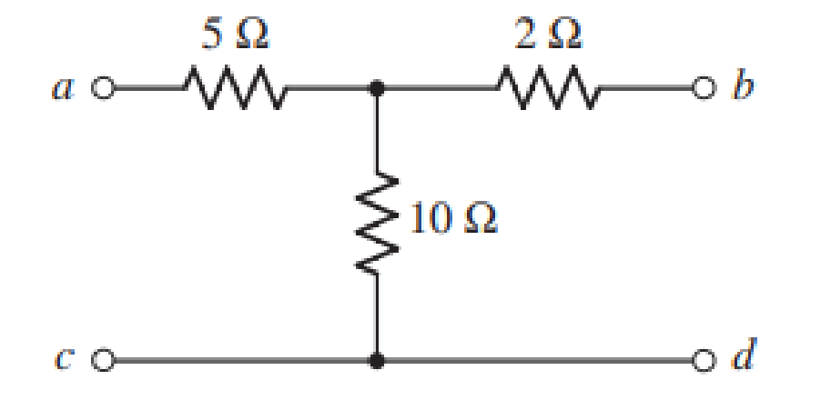
Chapter 16, Problem 60E
Four networks, each identical to the one depicted in Fig. 16.67, are connected in parallel such that all terminals labeled a are tied together, all terminals designated b are tied together, and all terminals labeled c and d are connected. Obtain the y, z, h, and t parameters which describe the parallel-connected network.
Expert Solution & Answer
Want to see the full answer?
Check out a sample textbook solution
Students have asked these similar questions
2-
For the network of Fig. 16.44:
a. Find the current I₁.
b. Calculate the voltage Veusing the voltage divider rule.
c. Find the voltage Vad
E 120 V 60°
R₁302
402
XL₂
Xc13 Ve
X1₂ 752
Determine the Y-parameters at a frequency of 10 kHz for the two-port network shown in
figure below. Present your answer in matrix form.
R1
5 Ohm
1 Ohm
400 μF
4 Ohm
R2
R3
C2
HE
200 μF
R5
L5
wome
5 Ohm
C4
796 µF
6.4 mH
Determine the Y-parameters at a frequency of 10 kHz for the two-port network shown in
figure below. Present your answer in matrix form.
R1
5 Ohm
1 Ohm
400 μF
R3
4 Ohm
R2
200 μF
R5
L5
mom.
5 Ohm
796 µF
6.4 mH
Chapter 16 Solutions
Loose Leaf for Engineering Circuit Analysis Format: Loose-leaf
Ch. 16.1 - Find the input impedance of the network shown in...Ch. 16.1 - Write a set of nodal equations for the circuit of...Ch. 16.2 - By applying the appropriate 1 V sources and short...Ch. 16.2 - Prob. 4PCh. 16.2 - Prob. 5PCh. 16.3 - Prob. 6PCh. 16.3 - Use Y and Y transformations to determine Rin for...Ch. 16.4 - Find z for the two-port shown in (a) Fig. 16.23a;...Ch. 16.4 - Prob. 9PCh. 16.5 - Prob. 10P
Ch. 16.5 - Prob. 11PCh. 16.6 - Prob. 12PCh. 16 - For the following system of equations, (a) write...Ch. 16 - With regard to the passive network depicted in...Ch. 16 - Determine the input impedance of the network shown...Ch. 16 - For the one-port network represented schematically...Ch. 16 - Prob. 6ECh. 16 - Prob. 7ECh. 16 - Prob. 8ECh. 16 - Prob. 9ECh. 16 - (a) If both the op amps shown in the circuit of...Ch. 16 - Prob. 11ECh. 16 - Prob. 12ECh. 16 - Prob. 13ECh. 16 - Prob. 14ECh. 16 - Prob. 15ECh. 16 - Prob. 16ECh. 16 - Prob. 17ECh. 16 - Prob. 18ECh. 16 - Prob. 19ECh. 16 - Prob. 20ECh. 16 - For the two-port displayed in Fig. 16.49, (a)...Ch. 16 - Prob. 22ECh. 16 - Determine the input impedance Zin of the one-port...Ch. 16 - Determine the input impedance Zin of the one-port...Ch. 16 - Employ Y conversion techniques as appropriate to...Ch. 16 - Prob. 26ECh. 16 - Prob. 27ECh. 16 - Prob. 28ECh. 16 - Compute the three parameter values necessary to...Ch. 16 - It is possible to construct an alternative...Ch. 16 - Prob. 31ECh. 16 - Prob. 32ECh. 16 - Prob. 33ECh. 16 - Prob. 34ECh. 16 - The two-port networks of Fig. 16.50 are connected...Ch. 16 - Prob. 36ECh. 16 - Prob. 37ECh. 16 - Obtain both the impedance and admittance...Ch. 16 - Prob. 39ECh. 16 - Determine the h parameters which describe the...Ch. 16 - Prob. 41ECh. 16 - Prob. 42ECh. 16 - Prob. 43ECh. 16 - Prob. 44ECh. 16 - Prob. 45ECh. 16 - Prob. 46ECh. 16 - Prob. 47ECh. 16 - Prob. 48ECh. 16 - Prob. 49ECh. 16 - Prob. 50ECh. 16 - (a) Employ suitably written mesh equations to...Ch. 16 - Prob. 52ECh. 16 - Prob. 53ECh. 16 - The two-port of Fig. 16.65 can be viewed as three...Ch. 16 - Consider the two separate two-ports of Fig. 16.61....Ch. 16 - Prob. 56ECh. 16 - Prob. 57ECh. 16 - Prob. 58ECh. 16 - (a) Obtain y, z, h, and t parameters for the...Ch. 16 - Four networks, each identical to the one depicted...Ch. 16 - A cascaded 12-element network is formed using four...Ch. 16 - Prob. 62ECh. 16 - Continuing from Exercise 62, the behavior of a ray...
Additional Engineering Textbook Solutions
Find more solutions based on key concepts
What is the color code for a 365- five-band precision resistor with a tolerance of 5 percent?
ELECTRICITY FOR TRADES (LOOSELEAF)
For the “tank” circuit in Fig. 14.79, find the resonant frequency.
Figure 14.79
For Probs. 14.39, 14.71, and 1...
Fundamentals of Electric Circuits
How many coulombs do 93.8 1016 electrons represent?
Principles Of Electric Circuits
Three point charges of equal magnitude q, that will yield a zero net electric field at the origin.
Engineering Electromagnetics
Does the severity of an electric shock increase ordecrease with eh of the following changes? a. A decrease in t...
Electric Motors and Control Systems
Design an ideal inverting op-amp circuit such that the voltage gain is Av=25 . The maximum current in any resis...
Microelectronics: Circuit Analysis and Design
Knowledge Booster


Learn more about
Need a deep-dive on the concept behind this application? Look no further. Learn more about this topic, electrical-engineering and related others by exploring similar questions and additional content below.Similar questions
- digital ckts. Q.2. Realize the following functions using minimum number of components to draw their digital circuits. 1. AB+ABAB 2 ABC + ABE + ABC 3. (A + B) (A + B) 4. (A+B+C). (A + 5 + c) (A + 3+C)arrow_forwardfind y-parameter for the circuit below. the subject is :two-port network 25n Jio2 n V2 V = (25+Jo) I, + 5I,arrow_forwardFor the following two-port circuit: 1- draw the input short circuit. 2- draw the output short circuit. 3- find the Y admittance Matrix values. If V1=10V & V2=5V: a- calculate I1, 12 b- current gain Gc C- voltage gain Gv d- power gain Gp 8 + V1 8 V2 Y11 Y12 12 Y21 Y22 V2 +arrow_forward
- 21. Find the voltage across terminals A and B of the circuit shown in Fig. 16. A 8 A 492. Figure 15 2 A 40 A B M 3 S 6 S Figure 16 4S 2S [5 V]arrow_forwardExercise: 1. Find 8-point DFT of the sequence x (n) = [1 2 3 44 32 1] by using two methods (direct and FFT)arrow_forwardTranslate News Maps YouTube Gmail M .JI d55 /12 u vx in the circuit shown in Fig. 4 equal to : 12448-Fig. 4.pdf A. 1.148 V В. 0.248 V C. 0.258 V D. 0.148 Varrow_forward
- Determine the 3-parameters of the two-port network below. 4 10052 tomm V₁ www 8452 15052 L₂ + V₂ 1arrow_forwardA combinational circuit has four inputs (A,B,C,D) and three outputs (X.Y,Z). XYZ represents a binary number whose value equals the number of 1's at the input. For example if ABCD=1011, XYZ=011.(a) find the minterm expansions for X,Y, and Z.(b) find the maxterm expansions for Y and Z.arrow_forwardYl dWl fatoom_basemsh Digital Circuits Lec 6 The institute of Samawa Technical First Year Department Information and Eng. Murtadha kamil Ali Communications Technology Homework: 1) Apply DeMorgan's theorems to each of the following expression A) (A+B+C)D B) ABC+DEF C) AB+CD+EF D) (A+B) +C E) (A+B) +CD F) (A+B)CD+E+F 2) Draw the logic circuit A) Y=(A+B+C)DE Y =ABCDE B) X= ACD+BC 3) The following figure gives the function A) B) LDS 59 ...luln Darrow_forward
- If x = [1 5 9 ; 2 7 4] , then a: display the last two elements by using disp command . b ) display the sum of each row as show below The sum of 1st row = The sum of 2nd rowarrow_forwardPlease explain. Also, do not use mesh analysis pleasearrow_forwardQ4. Use a Karnaugh map to minimize the following standard SOP expression: (15 M) ABC + ABC + ABC + ABC + ABC Q5. Plot the corresponding SUM and CARRY outputs of half-adder circuit, for the given A and B inputs. And give the logical expression for both. (15 M) HA A Barrow_forward
arrow_back_ios
SEE MORE QUESTIONS
arrow_forward_ios
Recommended textbooks for you
 Introductory Circuit Analysis (13th Edition)Electrical EngineeringISBN:9780133923605Author:Robert L. BoylestadPublisher:PEARSON
 Delmar's Standard Textbook Of ElectricityElectrical EngineeringISBN:9781337900348Author:Stephen L. HermanPublisher:Cengage Learning
 Programmable Logic ControllersElectrical EngineeringISBN:9780073373843Author:Frank D. PetruzellaPublisher:McGraw-Hill Education
 Fundamentals of Electric CircuitsElectrical EngineeringISBN:9780078028229Author:Charles K Alexander, Matthew SadikuPublisher:McGraw-Hill Education
 Electric Circuits. (11th Edition)Electrical EngineeringISBN:9780134746968Author:James W. Nilsson, Susan RiedelPublisher:PEARSON
 Engineering ElectromagneticsElectrical EngineeringISBN:9780078028151Author:Hayt, William H. (william Hart), Jr, BUCK, John A.Publisher:Mcgraw-hill Education,
Introductory Circuit Analysis (13th Edition)
Electrical Engineering
ISBN:9780133923605
Author:Robert L. Boylestad
Publisher:PEARSON
Delmar's Standard Textbook Of Electricity
Electrical Engineering
ISBN:9781337900348
Author:Stephen L. Herman
Publisher:Cengage Learning
Programmable Logic Controllers
Electrical Engineering
ISBN:9780073373843
Author:Frank D. Petruzella
Publisher:McGraw-Hill Education
Fundamentals of Electric Circuits
Electrical Engineering
ISBN:9780078028229
Author:Charles K Alexander, Matthew Sadiku
Publisher:McGraw-Hill Education
Electric Circuits. (11th Edition)
Electrical Engineering
ISBN:9780134746968
Author:James W. Nilsson, Susan Riedel
Publisher:PEARSON
Engineering Electromagnetics
Electrical Engineering
ISBN:9780078028151
Author:Hayt, William H. (william Hart), Jr, BUCK, John A.
Publisher:Mcgraw-hill Education,
Z Parameters - Impedance Parameters; Author: Electrical Engineering Authority;https://www.youtube.com/watch?v=qoD4AoNmySA;License: Standard Youtube License