
Loose Leaf for Engineering Circuit Analysis Format: Loose-leaf
9th Edition
ISBN: 9781259989452
Author: Hayt
Publisher: Mcgraw Hill Publishers
expand_more
expand_more
format_list_bulleted
Concept explainers
Videos
Textbook Question
Chapter 16, Problem 25E
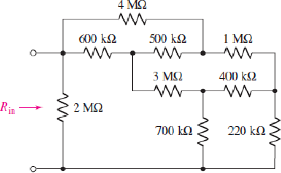
Employ Δ–Y conversion techniques as appropriate to determine the input resistance Rin of the one-port shown in Fig. 16.53.
Expert Solution & Answer
Want to see the full answer?
Check out a sample textbook solution
Students have asked these similar questions
Find the voltage R-2R DAC of 4bits with given condition of R = 6 kilo ohms, RF = 2 kilo ohms, VR = 16v and applied binary word is 1011.
1. Use the Design Procedure to design a device that will change serial data to parallel data:
Design a digital circuit that takes two 2-bit number A and B as input and generate four outputs F,
Q, Z and Y as follows
• If A is even number F=1
If B is even number Q=1.
• If A is equal to B Z=1.
If A is odd number Y=1.
Assume that you have access to limited number of AND, OR, NOT, XOR Gate.
Chapter 16 Solutions
Loose Leaf for Engineering Circuit Analysis Format: Loose-leaf
Ch. 16.1 - Find the input impedance of the network shown in...Ch. 16.1 - Write a set of nodal equations for the circuit of...Ch. 16.2 - By applying the appropriate 1 V sources and short...Ch. 16.2 - Prob. 4PCh. 16.2 - Prob. 5PCh. 16.3 - Prob. 6PCh. 16.3 - Use Y and Y transformations to determine Rin for...Ch. 16.4 - Find z for the two-port shown in (a) Fig. 16.23a;...Ch. 16.4 - Prob. 9PCh. 16.5 - Prob. 10P
Ch. 16.5 - Prob. 11PCh. 16.6 - Prob. 12PCh. 16 - For the following system of equations, (a) write...Ch. 16 - With regard to the passive network depicted in...Ch. 16 - Determine the input impedance of the network shown...Ch. 16 - For the one-port network represented schematically...Ch. 16 - Prob. 6ECh. 16 - Prob. 7ECh. 16 - Prob. 8ECh. 16 - Prob. 9ECh. 16 - (a) If both the op amps shown in the circuit of...Ch. 16 - Prob. 11ECh. 16 - Prob. 12ECh. 16 - Prob. 13ECh. 16 - Prob. 14ECh. 16 - Prob. 15ECh. 16 - Prob. 16ECh. 16 - Prob. 17ECh. 16 - Prob. 18ECh. 16 - Prob. 19ECh. 16 - Prob. 20ECh. 16 - For the two-port displayed in Fig. 16.49, (a)...Ch. 16 - Prob. 22ECh. 16 - Determine the input impedance Zin of the one-port...Ch. 16 - Determine the input impedance Zin of the one-port...Ch. 16 - Employ Y conversion techniques as appropriate to...Ch. 16 - Prob. 26ECh. 16 - Prob. 27ECh. 16 - Prob. 28ECh. 16 - Compute the three parameter values necessary to...Ch. 16 - It is possible to construct an alternative...Ch. 16 - Prob. 31ECh. 16 - Prob. 32ECh. 16 - Prob. 33ECh. 16 - Prob. 34ECh. 16 - The two-port networks of Fig. 16.50 are connected...Ch. 16 - Prob. 36ECh. 16 - Prob. 37ECh. 16 - Obtain both the impedance and admittance...Ch. 16 - Prob. 39ECh. 16 - Determine the h parameters which describe the...Ch. 16 - Prob. 41ECh. 16 - Prob. 42ECh. 16 - Prob. 43ECh. 16 - Prob. 44ECh. 16 - Prob. 45ECh. 16 - Prob. 46ECh. 16 - Prob. 47ECh. 16 - Prob. 48ECh. 16 - Prob. 49ECh. 16 - Prob. 50ECh. 16 - (a) Employ suitably written mesh equations to...Ch. 16 - Prob. 52ECh. 16 - Prob. 53ECh. 16 - The two-port of Fig. 16.65 can be viewed as three...Ch. 16 - Consider the two separate two-ports of Fig. 16.61....Ch. 16 - Prob. 56ECh. 16 - Prob. 57ECh. 16 - Prob. 58ECh. 16 - (a) Obtain y, z, h, and t parameters for the...Ch. 16 - Four networks, each identical to the one depicted...Ch. 16 - A cascaded 12-element network is formed using four...Ch. 16 - Prob. 62ECh. 16 - Continuing from Exercise 62, the behavior of a ray...
Additional Engineering Textbook Solutions
Find more solutions based on key concepts
The current source in the circuit shown generates the current pulse
Find (a) v (0); (b) the instant of time gr...
Electric Circuits. (11th Edition)
Does the severity of an electric shock increase ordecrease with eh of the following changes? a. A decrease in t...
Electric Motors and Control Systems
Electric power systems provide energy in a variety of commercial and industrial settings. Make a list of system...
Principles and Applications of Electrical Engineering
Write the nodal equations for the network of Fig. 8.137 using the general approach. Find the nodal voltages usi...
Introductory Circuit Analysis (13th Edition)
Design an ideal inverting op-amp circuit such that the voltage gain is Av=25 . The maximum current in any resis...
Microelectronics: Circuit Analysis and Design
Assume a telephone signal travels through a cable at two-thirds the speed of light. How long does it take the s...
Electric Circuits (10th Edition)
Knowledge Booster


Learn more about
Need a deep-dive on the concept behind this application? Look no further. Learn more about this topic, electrical-engineering and related others by exploring similar questions and additional content below.Similar questions
- Determine the Set of Inputs that will cause the Output Y = 1. NOT A NAND B NOR O- Y NOT NAND O A. A = 1, B = 0, C = 0, D= 1 O B. A = 1, B =1, C= 0, D=0 OC.A=0, B= 1, C= 0, D= 1 O D. A = 0, B = 0, C= 1, D= 1 O E. A = 0, B = 1, C= 1, D= 0arrow_forwardaabill (CME 446) 1 The admittance parameter Y12 in the 2-port network in Figure is 202 I2 I1 V1 V2 102 O a. -0.1 O b. None Oc.-0.2 Od. -0.05 O e. 0.05 Of.0.1arrow_forwardThe following two figures shows an input signal and output signal for a given circuit. Which of the following circuits in the options can achieve this. Input signal V+42.42 V ον АА M 16.67 m Output signal V+41.72 V ον 16.67 m O Transformer O Half wave rectifier O Inverter None of the above V-0.318 V-13.27 V Time, |arrow_forward
- ) Listen Consider the following JFET circuit. If Ip = 4.3 mA, the voltage at the gate is: %3D +V, DD +12V b (mA) 8.0 R 3.3 MQ Rp 8202 -6.0 4.0 R 1.5MQ Rs 1,0 kQ 2.0 VGS +3 VGS -2 -1 +1 +2 5.45 V MacBook Proarrow_forwardDesign a combinational circuit that accepts a four-bit number (A,B,C,D) and generates 3 output (X,Y,Z) which is equal to the sum of the binary numbers formed by the input (AB) * and (CD). HENT :(AB + CD = ??) إضافة ملفarrow_forwardQ16/ a combinational circuit has four inputs (A, B, C, D), which represent a binary- coded- decimal digit. The circuit has two groups of four outputs S, T, U, V, and W, X, Y, Z each group represents a BCD digit. The output digits represent a decimal number which is five times the input number. For example if ABCD=D0111, the output are 0011 0101. ASsume that invalid BCD digits do not occur as inputs. a- Construct the truth table b- Write minterms and max terms for all output C- Find SOP and POS for all outputarrow_forward
- 7 Find the input voltage and current in two-port at pic.7 if at short circuit output the ampermeter reading is Ia=10A, and coefficients A=3, B=12+j10 N, C=-j0,5S Uparrow_forwardCompute the DFT of the following finite length sequences. (Assume hat length is Nand N is even) 1) x[n] = 6 [n] x[n] = 5 [n– no] O Sam SN-1 n even x[n]= n oddarrow_forwardProblem #8) Determine the Thevenin's Equivalent Circuit parameters (Vn and Rm) for the single-port network shown below. Note- you must draw the circuits that you utilize when solving for the parameters. 12V www R₂ = 1402 R₁=10022 R₁-60 VTH RTH aarrow_forward
- Determine the step size for a 4-bit ADC having a range of 10V. Also, convert an analog sample of 3 V into the 4-bit digits using Successive approximation methodarrow_forwardIn the circuit shown below, X and Y are digital inputs, and Z is a digital output. The equivalent circuit is a X Y A XOR gate B D D NAND gate CXNOR gate NOR gate Zarrow_forward3. In the given figure below, the data rate for each input connection is 3 kbps. If 1 bit at a time is multiplexed (a unit is 1 bit), what is the duration of (a) each input slot, (b) each output slot, and (c) each frame? A3 A2 Al C3 B3;A3 C2HB2;A2 C1;BI HAI B3 B2 BI Frame 3 Frame 2 Frame I MUX Each frume is 3 time slots. Each time slot duration is T13 Data are taken from cach line every T's.arrow_forward
arrow_back_ios
SEE MORE QUESTIONS
arrow_forward_ios
Recommended textbooks for you
 Introductory Circuit Analysis (13th Edition)Electrical EngineeringISBN:9780133923605Author:Robert L. BoylestadPublisher:PEARSON
 Delmar's Standard Textbook Of ElectricityElectrical EngineeringISBN:9781337900348Author:Stephen L. HermanPublisher:Cengage Learning
 Programmable Logic ControllersElectrical EngineeringISBN:9780073373843Author:Frank D. PetruzellaPublisher:McGraw-Hill Education
 Fundamentals of Electric CircuitsElectrical EngineeringISBN:9780078028229Author:Charles K Alexander, Matthew SadikuPublisher:McGraw-Hill Education
 Electric Circuits. (11th Edition)Electrical EngineeringISBN:9780134746968Author:James W. Nilsson, Susan RiedelPublisher:PEARSON
 Engineering ElectromagneticsElectrical EngineeringISBN:9780078028151Author:Hayt, William H. (william Hart), Jr, BUCK, John A.Publisher:Mcgraw-hill Education,
Introductory Circuit Analysis (13th Edition)
Electrical Engineering
ISBN:9780133923605
Author:Robert L. Boylestad
Publisher:PEARSON
Delmar's Standard Textbook Of Electricity
Electrical Engineering
ISBN:9781337900348
Author:Stephen L. Herman
Publisher:Cengage Learning
Programmable Logic Controllers
Electrical Engineering
ISBN:9780073373843
Author:Frank D. Petruzella
Publisher:McGraw-Hill Education
Fundamentals of Electric Circuits
Electrical Engineering
ISBN:9780078028229
Author:Charles K Alexander, Matthew Sadiku
Publisher:McGraw-Hill Education
Electric Circuits. (11th Edition)
Electrical Engineering
ISBN:9780134746968
Author:James W. Nilsson, Susan Riedel
Publisher:PEARSON
Engineering Electromagnetics
Electrical Engineering
ISBN:9780078028151
Author:Hayt, William H. (william Hart), Jr, BUCK, John A.
Publisher:Mcgraw-hill Education,
Lecture 4b -- Transmission Line Parameters; Author: EMPossible;https://www.youtube.com/watch?v=naG572ZnXqw;License: Standard Youtube License