
Loose Leaf for Engineering Circuit Analysis Format: Loose-leaf
9th Edition
ISBN: 9781259989452
Author: Hayt
Publisher: Mcgraw Hill Publishers
expand_more
expand_more
format_list_bulleted
Videos
Textbook Question
Chapter 16, Problem 24E
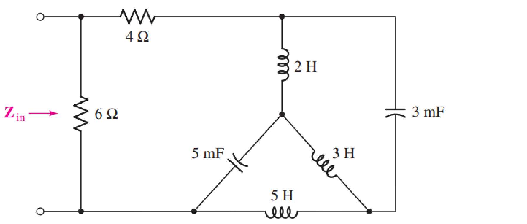
Determine the input impedance Zin of the one-port shown in Fig. 16.52 if ω is equal to (a) 50 rad/s; (b) 1000 rad/s.
Expert Solution & Answer
Want to see the full answer?
Check out a sample textbook solution
Students have asked these similar questions
1. The simplified expression of Y(ABC)= SUM(m0,m1,m2,m3,m4,m5,m6) is:
A. Y=A
B. Y=A'+B
C. Y=A'+B'+C'
D. Y=A'B
50
Find the frequency-domain values of
the Y-Parameters for the two-port circuit
shown?
V2
502
10Ω
-J20
V2
V1
4V1
1000
www
Home
Work!
SEATWORK 2
Show your complete solutions to the following problems and write it on a bond paper. Box your final answer. Scan your work and
submit a pdf file using File Upload.
For the two-port network shown
1H
1H
2F
V,
obtain the transfer function
A. V2(s) / V1(s)
B. V1(s) / 1(s)
Chapter 16 Solutions
Loose Leaf for Engineering Circuit Analysis Format: Loose-leaf
Ch. 16.1 - Find the input impedance of the network shown in...Ch. 16.1 - Write a set of nodal equations for the circuit of...Ch. 16.2 - By applying the appropriate 1 V sources and short...Ch. 16.2 - Prob. 4PCh. 16.2 - Prob. 5PCh. 16.3 - Prob. 6PCh. 16.3 - Use Y and Y transformations to determine Rin for...Ch. 16.4 - Find z for the two-port shown in (a) Fig. 16.23a;...Ch. 16.4 - Prob. 9PCh. 16.5 - Prob. 10P
Ch. 16.5 - Prob. 11PCh. 16.6 - Prob. 12PCh. 16 - For the following system of equations, (a) write...Ch. 16 - With regard to the passive network depicted in...Ch. 16 - Determine the input impedance of the network shown...Ch. 16 - For the one-port network represented schematically...Ch. 16 - Prob. 6ECh. 16 - Prob. 7ECh. 16 - Prob. 8ECh. 16 - Prob. 9ECh. 16 - (a) If both the op amps shown in the circuit of...Ch. 16 - Prob. 11ECh. 16 - Prob. 12ECh. 16 - Prob. 13ECh. 16 - Prob. 14ECh. 16 - Prob. 15ECh. 16 - Prob. 16ECh. 16 - Prob. 17ECh. 16 - Prob. 18ECh. 16 - Prob. 19ECh. 16 - Prob. 20ECh. 16 - For the two-port displayed in Fig. 16.49, (a)...Ch. 16 - Prob. 22ECh. 16 - Determine the input impedance Zin of the one-port...Ch. 16 - Determine the input impedance Zin of the one-port...Ch. 16 - Employ Y conversion techniques as appropriate to...Ch. 16 - Prob. 26ECh. 16 - Prob. 27ECh. 16 - Prob. 28ECh. 16 - Compute the three parameter values necessary to...Ch. 16 - It is possible to construct an alternative...Ch. 16 - Prob. 31ECh. 16 - Prob. 32ECh. 16 - Prob. 33ECh. 16 - Prob. 34ECh. 16 - The two-port networks of Fig. 16.50 are connected...Ch. 16 - Prob. 36ECh. 16 - Prob. 37ECh. 16 - Obtain both the impedance and admittance...Ch. 16 - Prob. 39ECh. 16 - Determine the h parameters which describe the...Ch. 16 - Prob. 41ECh. 16 - Prob. 42ECh. 16 - Prob. 43ECh. 16 - Prob. 44ECh. 16 - Prob. 45ECh. 16 - Prob. 46ECh. 16 - Prob. 47ECh. 16 - Prob. 48ECh. 16 - Prob. 49ECh. 16 - Prob. 50ECh. 16 - (a) Employ suitably written mesh equations to...Ch. 16 - Prob. 52ECh. 16 - Prob. 53ECh. 16 - The two-port of Fig. 16.65 can be viewed as three...Ch. 16 - Consider the two separate two-ports of Fig. 16.61....Ch. 16 - Prob. 56ECh. 16 - Prob. 57ECh. 16 - Prob. 58ECh. 16 - (a) Obtain y, z, h, and t parameters for the...Ch. 16 - Four networks, each identical to the one depicted...Ch. 16 - A cascaded 12-element network is formed using four...Ch. 16 - Prob. 62ECh. 16 - Continuing from Exercise 62, the behavior of a ray...
Additional Engineering Textbook Solutions
Find more solutions based on key concepts
Explain the main function of each of the following major components of a PLC: a. Processor module (CPU) b. I/O ...
Programmable Logic Controllers
Assume a telephone signal travels through a cable at two-thirds the speed of light. How long does it take the s...
Electric Circuits (10th Edition)
The current source in the circuit shown generates the current pulse
Find (a) v (0); (b) the instant of time gr...
Electric Circuits. (11th Edition)
The voltage source of the circuit shown in Fig. P1.29 is given by s(t)=25cos(4104t45)(V). Obtain an expression ...
Fundamentals of Applied Electromagnetics (7th Edition)
Design an ideal inverting op-amp circuit such that the voltage gain is Av=25 . The maximum current in any resis...
Microelectronics: Circuit Analysis and Design
When travelers from the USA and Canada visit Europe, they encounter a different power distribution system. Wall...
Electric machinery fundamentals
Knowledge Booster


Learn more about
Need a deep-dive on the concept behind this application? Look no further. Learn more about this topic, electrical-engineering and related others by exploring similar questions and additional content below.Similar questions
- Consider the given two-port where V=8 Vx NOTE: This is a multi-part question. Once an answer is submitted, you will be unable to return to this part. 911 912 102 921 922 V, Σ100 Ω 300 £2 ww where 911 5052 www ܠ Obtain the g parameters for the given network. [911 V O TS. 912-1 921 [ and 922 35.923 0arrow_forward16.20 a. Design a VCO as shown in Fig. 16.43(c) that has a nominal frequency of fo = 10 kHz. Assume Vcc = 15 V. D b. Calculate the modulation in the output frequencies if VCN is varied by ±10%. +Vcc R₂ VCN=Vcs+Ven Ven C3 R₂ C₂ 0.001 μF 5 R₁ NE/SE- 566 VCO C₁ 4 vo 1 www. 3—um Voarrow_forwardPractice: || Find Io in the following circuit using the concept of source transformation, 16.7 Jjarrow_forward
- 16.32 Design a V/F converter as shown in Fig. 16.64 so that fo = 2.5 kHz at v₁ = 5 V. The input voltage v₁ can vary between 10 mV and 10 V. Assume VDD = - Vss = 5 V. Vss=-5 V ** +5 V R₂ -5 V R₂ C3 0.1 μF Rc H Rin www HHII Rhias www Cref Vref -5 V 1 2 3 4 5 6 7 9400 V/F Cint не 14 13 12 11 10 9 8 + VDD = +5 V NC R₁ C4 0.01 μF R₁ VO2 ƒ/2 Vol fo VDD = +5 Varrow_forwardPractic: Find Io in tfo]]owincirusg cocep! of source transformation. 16.7 2 Jj VWA T s .288 /99.46° A.arrow_forward3) Find Thevenin's equivalent between terminal a&b for the circuit shown in Fig. 4A 14 JL 4 r. 1A $15L 201 5 SU 6 Aarrow_forward
- Consider the digital circuit shown below - B. Y D Compute the value of Y if A=1, B=1, and C=1,arrow_forward16.13 Determine i,(t) in the circuit of Fig. 1 F 2 H ell 2Ω A e-2u(t) A 1Ωarrow_forward16.29 Design the FSK modulator shown in Fig. 16.54(a) to produce frequencies of 1270 Hz and 1570 Hz corre- sponding to 1 (mark) and 0 (space), respectively. 1 1 Input digital data at 150 Hz VI Input digital serial data at 150 Hz RB 10 ΚΩ www Rc 50 ΚΩ Set at 39.24 ΚΩ FSK generator 1070-1270 Hz (a) AM/FM transmitter Q₁ 2N404 RA 50 ΚΩ Set at 41.51 ΚΩ RB 47 ΚΩ 0.01 μF HF 40 (b) Circuit 8 7 6 2 AM or FM transmitter Antenna Vcc = +5 V 4 NE/SE-555 3 C₁ 0.01 με 5 1070-1270 Hz Voarrow_forward
- 5- The S-parameters of a two-port network are measured by means of a: A-Spectrum Analyzer B-RF Oscilloscope C-RF Signal Generator D-Vector Network Analyzerarrow_forwardDetermine the Y-parameters at a frequency of 10 kHz for the two-port network shown in figure below. Present your answer in matrix form. R1 5 Ohm 1 Ohm 400 μF R3 4 Ohm R2 200 μF R5 L5 mom. 5 Ohm 796 µF 6.4 mHarrow_forwardGiven the voltage and current shown in Fig. 16.70, find the parallel network internal to the container. That is, find the actual value of each component using the provided frequency.arrow_forward
arrow_back_ios
SEE MORE QUESTIONS
arrow_forward_ios
Recommended textbooks for you
 Introductory Circuit Analysis (13th Edition)Electrical EngineeringISBN:9780133923605Author:Robert L. BoylestadPublisher:PEARSON
 Delmar's Standard Textbook Of ElectricityElectrical EngineeringISBN:9781337900348Author:Stephen L. HermanPublisher:Cengage Learning
 Programmable Logic ControllersElectrical EngineeringISBN:9780073373843Author:Frank D. PetruzellaPublisher:McGraw-Hill Education
 Fundamentals of Electric CircuitsElectrical EngineeringISBN:9780078028229Author:Charles K Alexander, Matthew SadikuPublisher:McGraw-Hill Education
 Electric Circuits. (11th Edition)Electrical EngineeringISBN:9780134746968Author:James W. Nilsson, Susan RiedelPublisher:PEARSON
 Engineering ElectromagneticsElectrical EngineeringISBN:9780078028151Author:Hayt, William H. (william Hart), Jr, BUCK, John A.Publisher:Mcgraw-hill Education,
Introductory Circuit Analysis (13th Edition)
Electrical Engineering
ISBN:9780133923605
Author:Robert L. Boylestad
Publisher:PEARSON
Delmar's Standard Textbook Of Electricity
Electrical Engineering
ISBN:9781337900348
Author:Stephen L. Herman
Publisher:Cengage Learning
Programmable Logic Controllers
Electrical Engineering
ISBN:9780073373843
Author:Frank D. Petruzella
Publisher:McGraw-Hill Education
Fundamentals of Electric Circuits
Electrical Engineering
ISBN:9780078028229
Author:Charles K Alexander, Matthew Sadiku
Publisher:McGraw-Hill Education
Electric Circuits. (11th Edition)
Electrical Engineering
ISBN:9780134746968
Author:James W. Nilsson, Susan Riedel
Publisher:PEARSON
Engineering Electromagnetics
Electrical Engineering
ISBN:9780078028151
Author:Hayt, William H. (william Hart), Jr, BUCK, John A.
Publisher:Mcgraw-hill Education,
Introduction to Two-Port Networks; Author: ALL ABOUT ELECTRONICS;https://www.youtube.com/watch?v=ru2ItcD6unI;License: Standard Youtube License