
Videos
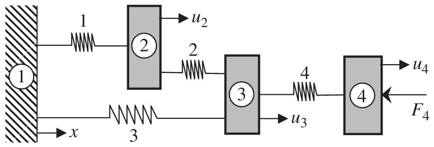
Three rigid bodies, 2,3, and 4, are connected by four springs as shown in the figure. A horizontal force of 1,000 N is applied on body 4 as shown in the figure. Find the displacements of the three bodies and the forces (tensile/compressive) in the springs. What is the reaction at the wall? Assume the bodies can undergo only translation in the horizontal direction. The spring constants (N/mm) are:
Want to see the full answer?
Check out a sample textbook solution
Chapter 1 Solutions
Introduction To Finite Element Analysis And Design
Additional Engineering Textbook Solutions
DeGarmo's Materials and Processes in Manufacturing
Automotive Technology: Principles, Diagnosis, and Service (5th Edition)
Thinking Like an Engineer: An Active Learning Approach (3rd Edition)
Degarmo's Materials And Processes In Manufacturing
Fundamentals of Heat and Mass Transfer
Heating Ventilating and Air Conditioning: Analysis and Design


- Two rigid bars are connected to each other by two linearly elastic springs. Before loads are applied, the lengths or the springs are such, that the bars are parallel and the springs are without stress. (a) Derive a formula for the displacement E4at point 4 when the load P is applied at joint 3 and moment PL is applied at joint 1. as shown in the figure part a. (Assume that the bars rotate through very small angles under the action of load P.) (b) Repeat part (a) if a rotational spring, kr= kL2, is now added at joint 6. What is the ratio of the deflection d4 in the figure part a to that in the figure part b ?arrow_forwardA uniform bar AB of weight W = 25 N is supported by two springs, as shown in the figure. The spring on the left has a stiffness k[= 300 N/m and natural length Lt=250 mm. The corresponding quantities for the spring on the right are k2= 400 N/m and L^ = 200 mm. The distance between the springs is L = 350 mm, and the spring on the right is suspended from a support that is a distance it = SO mm below the point of support for the spring on the left. Neglect the weight of the springs. (a) At what distance x from the left-hand spring (figure part a) should a load P = 18 N be placed in order to bring the bar to a horizontal position? (b) If P is now removed, what new value of k{is required so that the bar (figure part a) will hang in a horizontal position underweight If? (c) If P is removed and kt= 300 N/m. what distance b should spring ktbe moved to the right so that the bar (figure part a) will hang in a horizontal position under weight II"? (d) If the spring on the left is now replaced by two springs in series (kt= 300 N/m, kt) with overall natural length Lt= 250 mm (see figure part b). what value of k; is required so that the bar will hang in a horizontal position under weight IF?arrow_forwardA polyethylene tube (length L) has a cap that when installed compresses a spring (with under-formed length L1) by an amount ?? = (L1 = L). Ignore deformations of the cap and base. Use the force at the base of the spring as the redundant. Use numerical properties given in the boxes. (a) What is the resulting Force-in the spring, Fk? (b) What is the resulting Force in the tube, Ftl (c) What is the filial length of the tube, Lf? (d) What temperature change ?T inside the tube will result in zero force in the springarrow_forward
- A bar ABC revolves in a horizontal plane about a vertical axis at the midpoint C (see figure). The bar, which has a length 2L and crass-sectional area A, revolves at constant angular speed at. Each half of the bar (AC and BC) has a weight W, and supports a weight W2at its end. Derive the following formula for the elongation of one-half of the bar (that is. the elongation of either AC ar BC). =L223gEA(w1+3w2) in which E is t he modulus of elasticity of the material of the bar and g is the acceleration of gravity.arrow_forwardSolve the preceding problem if the collar has mass M = 80 kg, the height h = 0.5 m, the length L = 3.0 m, the cross-sectional area A = 350mm2. and the modulus of elasticity E = 170 GPa.arrow_forwardA round bar ABC of length 2L (see figure) rotates about an axis through the midpoint C with constant angular speed w (radians per second). The material of the bar has weight density y. (a) Derive a formula for the tensile stress a’ in the bar as a function of the distance x from the midpoint C. (b) What is the maximum tensile stress a max?arrow_forward
- A bumper for a mine car is constructed with a spring of stiffness k = 1120 lb/in. (see figure). If a car weighing 3450 lb is traveling at velocity v = 7 mph when it strikes the spring, what is the maximum shortening of the spring?arrow_forwardBy what distance h does the cage shown in the figure move downward when the weight W is placed inside it? (See the figure.) Consider only the effects of the stretching of the cable, which has axial rigidity EA = 10,700 kN. The pulley at A has a diameter da= 300 mm and the pulley at B has a diameter dB= 150 mm. Also, the distance L1= 4.6 m, the distance L2=10.5 m, and the weight W = 22 kN. Note: When calculating the length of the cable. include the parts of the cable that go around the pulley sat A and B.arrow_forwardThe device shown in the figure consists of a prismatic rigid pointer ABC supported by a uniform translational spring of stiffness k = 950 N/m. The spring is positioned a distance P = 165 nun from the pinned end A of the pointer. The device is adjusted so that, when there is no load P, the pointer reads zero on the angular scale. (a) If the load P = 11 N, al what distance .v should the load be placed so that the pointer will read ?? = 2.5° on the scale (see figure part a)? (b) Repeal part (a) if a rotational spring E1= kb-6 is added al A (see figure part b). (c) Lel.x = 7b/8.What is P maxif 0 cannot exceed 2"? Include spring krin your analysis. (d) Now, if the weight of the pointer ABC is known to be W =3N and the weight or the spring is Ws= 2.75 N, what initial angular position (Left in degrees) of the pointer will result in a zero reading on the angular scale once the pointer is released from rest? Assume P = kr=0. (e) If the pointer is rotated lo a vertical position (see figure part c), find the required load P applied at mid-height of the pointer that will result in a pointer reading of 0 = 2.5" on the scale. Consider the weight of the pointer W. in your analysis.arrow_forward
- Solve the preceding problem for the following data: b = 6 in., b = 10 in, L = 110 ft, tan a = 1/3, and q = 325 lb/ft.arrow_forwardA circular bar ACB of a diameter d having a cylindrical hole of length .r and diameter till from A to C is held between rigid supports at A and B. A load P acts at U2from ends A and B. Assume E is constant. (a) Obtain formulas for the reactions R, and RBat supports A and B. respectively, due to the load P (see figure part a). (b) Obtain a formula for the displacement S at the point of load application (see figure part a). (c) For what value of x is RB= (6/5)?,? (See figure part a.) (d) Repeat part (a) if the bar is now rotated to a vertical position, load P is removed, and the bar is hanging under its own weight (assume mass density = p). (See figure part b.) Assume that x = LI2.arrow_forwardSolve the preceding problem for the following data: b = 8.0 in., k = 16 lb/in., a = 45°, and P = 10 lb.arrow_forward
 Mechanics of Materials (MindTap Course List)Mechanical EngineeringISBN:9781337093347Author:Barry J. Goodno, James M. GerePublisher:Cengage Learning