
Introduction To Finite Element Analysis And Design
2nd Edition
ISBN: 9781119078722
Author: Kim, Nam H., Sankar, Bhavani V., KUMAR, Ashok V., Author.
Publisher: John Wiley & Sons,
expand_more
expand_more
format_list_bulleted
Concept explainers
Videos
Textbook Question
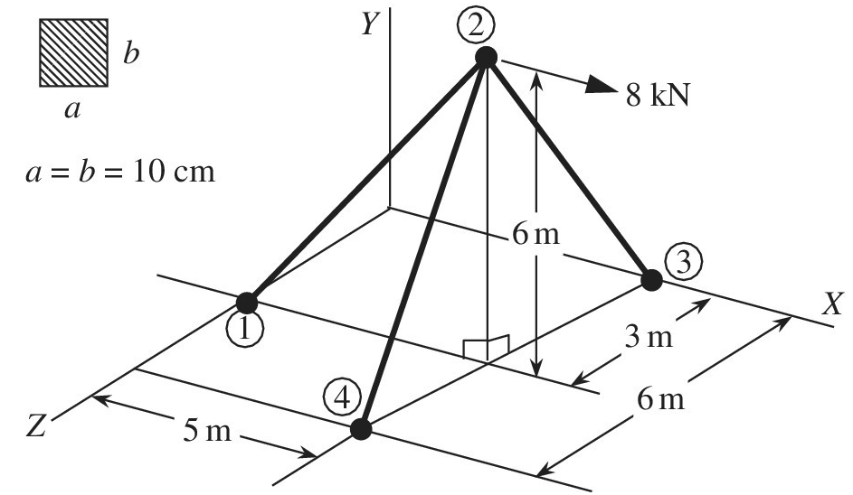
Chapter 1, Problem 35E
Determine the normal stress in each member of the truss structure. All joints are ball joint, and the material is steel whose Young’s modulus is
Expert Solution & Answer
Want to see the full answer?
Check out a sample textbook solution
Students have asked these similar questions
Three wood boards, each 4
inches wide, are joined by the 4-inch
diameter bolt. If the working stresses for
wood are 800 psi (pounds per square inch)
in tension , find the value of the force P (Ibs)
that maybe applied to the joint.
I in.
2 in.
1 in.
- Fin.
A
12
60°
B
2.7 m
The strut is supported by a pin at C and an A-36 steel (Young's Modulus is 200 GPa) guy wire
AB. If the wire has a diameter of 5 mm, determine how much it stretches when the distributed
load acts on the strut.
Q2. The pin-connected frame is subjected to the force Fas shown. The dimensions
are 4-4.0 ft, - 2.6 ft. and -3.9 ft. Member BC is made of steel (E- 29000 ksi),
and has rectangular cross-section, with b- 13 in. and h=4.1 in. The supports at B
and Cact as pins for x-x axis buckling and as fixed supports for y yaxis buckling.
Determine the greatest load F(in the unit of kip) the beam will support without
causing member BC to buckle.
Please pay attention: the numbers may change since they are randomized. Your
answer must include 2 places after the decimal point.
Your Answer:
Chapter 1 Solutions
Introduction To Finite Element Analysis And Design
Ch. 1 - Answer the following descriptive questions a....Ch. 1 - Calculate the displacement at node 2 and reaction...Ch. 1 - Repeat problem 2 by changing node numbers; that...Ch. 1 - Three rigid bodies, 2,3, and 4, are connected by...Ch. 1 - Three rigid bodies, 2,3, and 4, are connected by...Ch. 1 - Consider the spring-rigid body system described in...Ch. 1 - Four rigid bodies, 1, 2, 3, and 4, are connected...Ch. 1 - Determine the nodal displacements, element forces,...Ch. 1 - In the structure shown, rigid blocks are connected...Ch. 1 - The spring-mass system shown in the figure is in...
Ch. 1 - A structure is composed of two one-dimensional bar...Ch. 1 - Two rigid masses, 1 and 2, are connected by three...Ch. 1 - Use the finite element method to determine the...Ch. 1 - Consider a tapered bar of circular cross section....Ch. 1 - The stepped bar shown in the figure is subjected...Ch. 1 - Using the direct stiffness matrix method, find the...Ch. 1 - A stepped bar is clamped at one end and subjected...Ch. 1 - A stepped bar is clamped at both ends. A force of ...Ch. 1 - Repeat problem 18 for the stepped bar shown in the...Ch. 1 - The finite element equation for the uniaxial bar...Ch. 1 - The truss structure shown in the figure supports a...Ch. 1 - The properties of the two elements of a plane...Ch. 1 - For a two-dimensional truss structure as shown in...Ch. 1 - The 2D truss shown in the figure is assembled to...Ch. 1 - For a two-dimensional truss structure as shown in...Ch. 1 - The truss shown in the figure supports force Fat...Ch. 1 - Prob. 27ECh. 1 - In the finite element model of a plane truss in...Ch. 1 - Use the finite element method to solve the plane...Ch. 1 - The plane truss shown in the figure has two...Ch. 1 - Two bars are connected as shown in the figure....Ch. 1 - The truss structure shown in the figure supports...Ch. 1 - It is desired to use the finite element method to...Ch. 1 - Determine the member force and axial stress in...Ch. 1 - Determine the normal stress in each member of the...Ch. 1 - The space truss shown has four members. Determine...Ch. 1 - The uniaxial bar shown below can be modeled as a...Ch. 1 - In the structure shown below, the temperature of...Ch. 1 - Prob. 39ECh. 1 - The three-bar truss problem in figure 1.23 is...Ch. 1 - Use the finite element method to determine the...Ch. 1 - Repeat problem 41 for the new configuration with...Ch. 1 - Repeat problem 42 with an external force added to...Ch. 1 - The properties of the members of the truss in the...Ch. 1 - Repeat problem 44 for the truss on the right side...Ch. 1 - The truss shown in the figure supports the force ....Ch. 1 - The finite element method as used to solve the...Ch. 1 - Prob. 48E
Additional Engineering Textbook Solutions
Find more solutions based on key concepts
Liquid ammonia has a specific gravity of 0.826. Calculate the volume in cm3 that would weigh 5.0 lb.
Applied Fluid Mechanics (7th Edition)
As an employee of the Los Angeles Air Quality Commission, you have been asked to develop a model for computing ...
Fundamentals of Heat and Mass Transfer
The y component of velocity in a two-dimensional, incompressible flow field is given by υ = − Axy, where υ is i...
Fox and McDonald's Introduction to Fluid Mechanics
What are the two different gas flows in plasma arc welding?
DeGarmo's Materials and Processes in Manufacturing
To drawthe thermal circuit and to mention each resistance element.
Introduction to Heat Transfer
The uniform plate has a weight of 500 lb. Determine the tension in each of the supporting cables. Prob. F5-7
INTERNATIONAL EDITION---Engineering Mechanics: Statics, 14th edition (SI unit)
Knowledge Booster


Learn more about
Need a deep-dive on the concept behind this application? Look no further. Learn more about this topic, mechanical-engineering and related others by exploring similar questions and additional content below.Similar questions
- Q) For the shown truss, determine the stiffness matrix of member 1 (1 to 3) and member 2 (2 to 3)? Let A = 50X10 m² and E-210 GPa for all elements. 50 KN 30 m - 3 20 m 100 KN 30 m 40 marrow_forwardA new art exhibit featuring mobile works is going up in the Norwalk, CA area. One art work is shown in the figure below. A 105 N uniform beam is pinned to the ground by a pivot. The beam is supported by a cable (attached 3/5 from the bottom of the beam) to allow for each of the shoes to hang freely. Each individual shoe has a weight of 7.5 N. 10 WALL FLOR (a) ( If one shoe is attached 1/7 of the way up the beam and another shoe is attached 5/8 of the way up the beam, with e, = 70.1° and e, 30.1°, what is the tension in the cable, in newtons? %3! %3D (b) What is the x-component of the force, in newtons, that the pivot exerts on the bottom of the beam? (c) O What is the y-component of the force, in newtons, that the pivot exerts on the bottom of the beam?arrow_forwardFind the load on each bar of the cage given below. Its dimensions are base 2a and height 3a. EB passes through the midpoint of the lattice. Angle of force F1= 700 with horizontal (choose an angle between 15o and 75o)arrow_forward
- A compressive load of 219 kN is resisted by a rectangular strut which has one side measuring 83 mm. If the stress in the strut is 164 909 kPa, what is the length of the other side of the strut?arrow_forward1. Find the load in members AD and AE for the truss shown in the figure. Use last three digits of your ID for the load P 87 KN 1.5 m 2 m C 2 m 120 KN 3m E 4.5 m 2 m PKN amongarrow_forwardA11 Estimate the matrix of the structure to solve with the method of knots. Determine the stresses in each bar and the link reactions.arrow_forward
- The 7/8-in.-diameter pins at A and C that support the structure are in single shear. Find the largest force F that can be applied to the structure if the working shear stress for these pins is 5000 psi. Neglect the weights of the members. Please only respond to this questions - Solve for F considering member BC. -Evaluate and compare obtained values of F and choose the maximum allowable load for the structure.arrow_forward2 T « A solid round bar 60 mm in diameter and 2.5 m long is used as a strut. One. of the strut is fixed, while its other end is hinged. Find the safe compressive load for this strut, 4 gEuIef'S formula. Assume E = 200 GN/m? and factor of safety = 3. Sarrow_forwardA new art exhibit featuring mobile works is going up in the Holland, MI, area. One piece is shown in the figure. The 155-N uniform beam is pinned to the ground by a pivot. The beam is supported by a cable (attached to the center of the beam) to allow for each of the shoes to hang freely. Each individual shoe has a weight of 9.5-N. If one shoe is attached two-fifths of the way up the beam and another shoe is attached and three-fifths of the way up the beam, with θc = 16.5° and θb = 33.6° as shown in the figure, what is the tension in the cable, in newtons? What is the x-component of the force, in newtons, that the pivot exerts on the bottom of the beam? Use the coordinate system specified in the figure. What is the y-component of the force, in newtons, that the hinge exerts on the bottom of the beam? Use the coordinate system specified in the figure.arrow_forward
- The horizontal link BC is 1/4 in. Of thickness and width w = 1.25 in., It is made of steel with an ultimate tensile strength of 65 ksi. What is the factor of safety if the structure shown was designed to support a load P 10 kips?arrow_forwardA straight girder of uniform section and length L rests on supports at the ends, and is propped up by a third support in the middle. The weight of the girder and its load is w per unit length. If the central support does not yield, prove that it takes a load equal to (5/8)wL. ANSWER: 1.80cm and 2.48cm Please show solution to the answer.arrow_forwardThe truss below is subject to the loads as shown. All of the members are attached at plates and can be treated as pin connected. The truss is attached to the ground with a pin joint at A and a roller at E The applied load H is 335 lb. The applied load J is 211 lb. What is the internal resultant normal force in member CD in lb? (tension is positive, compression is negative) J H B A 1.5ft 3ft D E 3ft 3ftarrow_forward
arrow_back_ios
SEE MORE QUESTIONS
arrow_forward_ios
Recommended textbooks for you
 Mechanics of Materials (MindTap Course List)Mechanical EngineeringISBN:9781337093347Author:Barry J. Goodno, James M. GerePublisher:Cengage Learning
Mechanics of Materials (MindTap Course List)
Mechanical Engineering
ISBN:9781337093347
Author:Barry J. Goodno, James M. Gere
Publisher:Cengage Learning
Everything About COMBINED LOADING in 10 Minutes! Mechanics of Materials; Author: Less Boring Lectures;https://www.youtube.com/watch?v=N-PlI900hSg;License: Standard youtube license