
Mechanics of Materials (10th Edition)
10th Edition
ISBN: 9780134319650
Author: Russell C. Hibbeler
Publisher: PEARSON
expand_more
expand_more
format_list_bulleted
Videos
Textbook Question
Chapter 9.4, Problem 9.66P
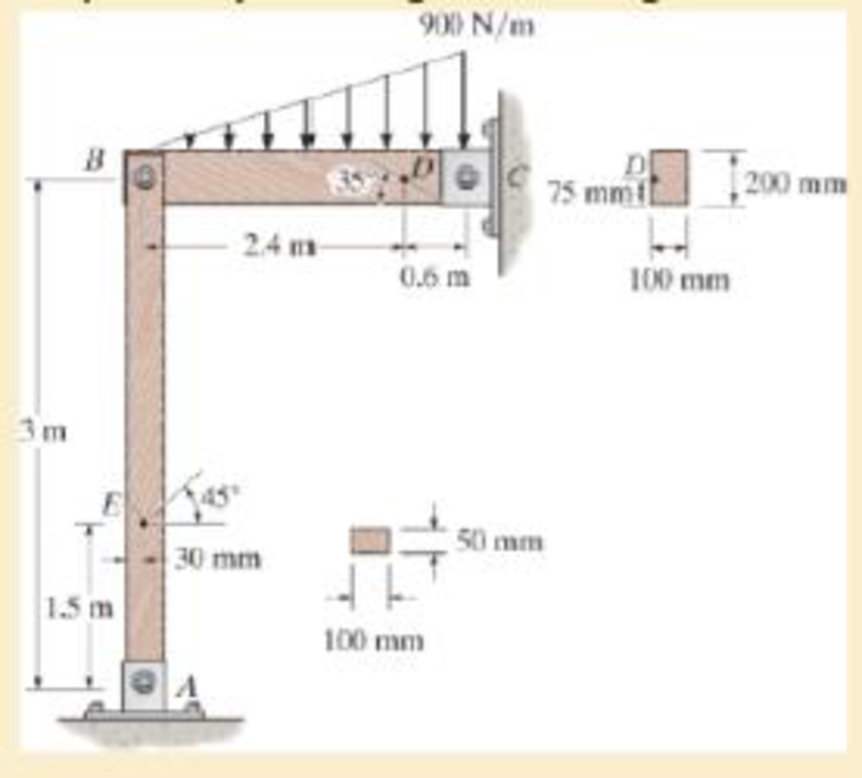
The frame supports the triangular distributed load shown. Determine the normal and shear stresses at point D that act perpendicular and parallel, respectively, to the grains. The grains at this point make an angle of 35° with the horizontal as shown.
Expert Solution & Answer

Trending nowThis is a popular solution!

Students have asked these similar questions
Determine the normal and shear stresses at point D that act perpendicular and parallel, respectively, to the grains. The grains at this point make an angle of 30° with the horizontal as shown. Point D is located just to the left of the 10-kN force
The wood grains on the board shown below form an angle of 20° with the horizontal. using the circle of Mohr, determine the normal and shearing stresses acting perpendicularly and parallel to the grains if the plate is subjected to an axial load of 250 N.
Use Mohrs circle to find the principle stresses and determine the normal and shear stresses acting on a plane 45 degrees counter clockwise from the Y-plane. Sketch showing the exterior stresses.
Chapter 9 Solutions
Mechanics of Materials (10th Edition)
Ch. 9.3 - In each case, the state of stress x, y, xy...Ch. 9.3 - Given the state of stress shown on the element,...Ch. 9.3 - Determine the normal stress and shear stress...Ch. 9.3 - Determine the equivalent state of stress on an...Ch. 9.3 - Also, find the corresponding orientation of the...Ch. 9.3 - Determine the equivalent state of stress on an...Ch. 9.3 - Determine the maximum principal stress at point B.Ch. 9.3 - Determine the principal stress at point C.Ch. 9.3 - Prove that the sum of the normal stresses x + y =...Ch. 9.3 - Determine the stress components acting on the...
Ch. 9.3 - Determine the stress components acting on the...Ch. 9.3 - Determine the normal stress and shear stress...Ch. 9.3 - Determine the normal stress and shear stress...Ch. 9.3 - Determine the stress components acting on the...Ch. 9.3 - Determine the stress components acting on the...Ch. 9.3 - Solve Prob.97 using the stress transformation...Ch. 9.3 - Determine the stress components acting on the...Ch. 9.3 - Solve Prob.99 using the stress transformation...Ch. 9.3 - Determine the equivalent state of stress on an...Ch. 9.3 - Determine the equivalent slate of stress on an...Ch. 9.3 - Determine the stress components acting on the...Ch. 9.3 - Determine (a) the principal stresses and (b) the...Ch. 9.3 - The state of stress at a point is shown on the...Ch. 9.3 - Determine the equivalent state of stress on an...Ch. 9.3 - Determine the equivalent state of stress on an...Ch. 9.3 - A point on a thin plate is subjected to the two...Ch. 9.3 - Determine the equivalent state of stress on an...Ch. 9.3 - The stress along two planes at a point is...Ch. 9.3 - The stress acting on two planes at a point is...Ch. 9.3 - The state of stress at a point in a member is...Ch. 9.3 - The grains of wood in the board make an angle of...Ch. 9.3 - The wood beam is subjected to a load of 12 kN. If...Ch. 9.3 - The internal loadings at a section of the beam are...Ch. 9.3 - Solve Prob.925 for point B. 925. The internal...Ch. 9.3 - Solve Prob.925 for point C. 925. The internal...Ch. 9.3 - It is subjected to a torque of 12 kip in. and a...Ch. 9.3 - The bell crank is pinned at A and supported by a...Ch. 9.3 - The beam has a rectangular cross section and is...Ch. 9.3 - A paper tube is formed by rolling a cardboard...Ch. 9.3 - Solve Prob.931 for the normal stress acting...Ch. 9.3 - The 2-in.-diameter drive shaft AB on the...Ch. 9.3 - Determine the principal stresses in the...Ch. 9.3 - The internal loadings at a cross section through...Ch. 9.3 - The internal loadings at a cross section through...Ch. 9.3 - The shaft has a diameter d and is subjected to the...Ch. 9.3 - The steel pipe has an inner diameter of 2.75 in....Ch. 9.3 - Solve Prob.938 for point B, w1ich is located on...Ch. 9.3 - The wide-flange beam is subjected to the 50-kN...Ch. 9.3 - Solve Pro b. 9-40 for point B located on the web...Ch. 9.3 - The box beam is subjected to the 26-kN force that...Ch. 9.3 - Solve Prob.942 for point B. 942. The box beam is...Ch. 9.4 - Use Mohrs circle to determine the normal stress...Ch. 9.4 - Also, find the corresponding orientation of the...Ch. 9.4 - Draw Mohrs circle and determine the principal...Ch. 9.4 - Determine the principal stresses at a point on the...Ch. 9.4 - Determine the principal stresses at point A on the...Ch. 9.4 - Point A is just below the flange.Ch. 9.4 - Solve Prob.9-2 using Mohrs circle. 92. Determine...Ch. 9.4 - Solve Prob.93 using Mohrs circle. 93. Determine...Ch. 9.4 - Solve Prob.96 using Mohrs circle. 96. Determine...Ch. 9.4 - Solve Prob.911 using Mohrs circle. 911. Determine...Ch. 9.4 - Solve Prob.915 using Mohrs circle. 915. The state...Ch. 9.4 - Solve Prob.916 using Mohrs circle. 916. Determine...Ch. 9.4 - Mohrs circle for the state of stress is shown in...Ch. 9.4 - Determine (a) the principal stresses and (b) the...Ch. 9.4 - Determine (a) the principal stresses and (b) the...Ch. 9.4 - Determine the equivalent state of stress if an...Ch. 9.4 - Draw Mohrs circle that describes each of the...Ch. 9.4 - Draw Mohrs circle trial describes each of the...Ch. 9.4 - Determine (a) the principal stresses and (b) the...Ch. 9.4 - Determine (a) the principal stresses and (b) the...Ch. 9.4 - Determine (a) the principal stresses and (b) the...Ch. 9.4 - Determine (a) the principal stresses and (b) the...Ch. 9.4 - Determine (a) the principal stresses and (b) the...Ch. 9.4 - Draw Mohrs circle that describes each of the...Ch. 9.4 - The grains of wood in the board make an angle of...Ch. 9.4 - The post is fixed supported at its base and a...Ch. 9.4 - Determine the principal stresses, the maximum...Ch. 9.4 - The thin-walled pipe has an inner diameter of 0.5...Ch. 9.4 - The frame supports the triangular distributed load...Ch. 9.4 - The frame supports the triangular distributed load...Ch. 9.4 - The rotor shaft of the helicopter is subjected to...Ch. 9.4 - The pedal crank for a bicycle has the cross...Ch. 9.4 - A spherical pressure vessel has an inner radius of...Ch. 9.4 - The cylindrical pressure vessel has an inner...Ch. 9.4 - Determine the normal and shear stresses at point D...Ch. 9.4 - Determine the principal stress at point D, Which...Ch. 9.4 - If the box wrench is subjected to the 50 lb force,...Ch. 9.4 - If the box wrench is subjected to the 50-lb force,...Ch. 9.4 - The post is fixed supported at its base and the...Ch. 9.5 - Draw the three Mohrs circles that describe each of...Ch. 9.5 - Draw the three Mohrs circles that describe the...Ch. 9.5 - Draw the three Mohrs circles that describe the...Ch. 9.5 - Determine the principal stresses and the absolute...Ch. 9.5 - Determine the principal stresses and the absolute...Ch. 9.5 - Determine the principal stresses and the absolute...Ch. 9.5 - Determine the principal stresses and the absolute...Ch. 9.5 - The solid shaft is subjected to a torque, bending...Ch. 9.5 - The frame is subjected to a horizontal force and...Ch. 9.5 - The bolt is fixed to its support at C. If a force...Ch. 9.5 - The bolt is fixed to its support at C. If a force...Ch. 9 - Prob. 9.1RPCh. 9 - The steel pipe has an inner diameter of 2.75 in....Ch. 9 - Determine the equivalent state of stress If an...Ch. 9 - The crane is used to support the 350-lb load....Ch. 9 - Determine the equivalent state of stress on an...Ch. 9 - The propeller shaft of the tugboat is subjected to...Ch. 9 - Determine the principal stresses in the box beam...Ch. 9 - Determine (a) the principal stresses and (b) the...Ch. 9 - Determine the stress components acting on the...
Knowledge Booster


Learn more about
Need a deep-dive on the concept behind this application? Look no further. Learn more about this topic, mechanical-engineering and related others by exploring similar questions and additional content below.Similar questions
- The internal loadings at a section of the beam are shown. Determine the in-plane principal stresses at point A. Also, compute the maximum in-plane shear stress at this point.arrow_forwardUse Mohr’s circle to determine the principal stresses at the point. Also, find the corresponding orientation of the element with respect to the element shown.arrow_forwardDetermine the principal planes and the principal stresses for the state of plane stress resulting from the superposition of the two states of stress shown. Given: X = 60 MPa and Y = 20 MPa. Determine the orientation of the principal plane in the first and second quadrant. Determine the maximum/minimum principal stressesarrow_forward
- The grains of wood in the board make an angle of 20° with the horizontal as shown. Determine the normal and shear stresses that act perpendicular and parallel to the grains if the board is subjected to an axial load of 250 N.arrow_forwardConsider the general case of plane stress as shown. Write a computer program that will show a plot of the three Mohr’s circles for the element, and will also determine the maximum in-plane shear stress and the absolute maximumshear stress.arrow_forward6kN and 1.0KNM loads are applied to the top of the 62-mm-diameter cast-iron as shown. Determine the principal stresses (max and min normal stresses), principal planes (orientation of plane for max-min normal stresses) and max shear stress by using Mohr's circle. Hint: Use given coordinate system. So, H is on x-z plane and K is on y- z plane 1.0 kN.m 6 kN X 220 mmarrow_forward
- The main stress, the maximum shear stress, and the dead angle are obtained when the stress is given as shown in the picture below.Draw Mohr's circle.arrow_forwardThe 20 mm diameter rod is subjected to the loads shown. (a) Determine the state of stress at point A and show the results on a differential element located at this point. (b) Using Mohr's circle, determine the maximum normal stress and the maximum in-plane shearing stress at point A and show the associated stress states on appropriately oriented elements, for each case. 75 mm 375 N B 200 mm 450 Narrow_forwardTwo forces are applied on the beam shown below. (a) Determine the normal and shear stresses at point B on the shown cross-section. (b) Show the state of stress at the point B on a volume element. 400 lb B 1 in. 2 in. 500 Ib 2 in 10 in. 1.5 in. 1.5 in. Show your steps and highlight the following answers please I =arrow_forward
- Use Mohr’s circle to determine the normal stress and shear stress acting on the inclined plane AB.arrow_forward1. The pictured link acts as a part of the elevator control for a small airplane. If the attached aluminum tube has an inner diameter of 25 mm and a wall thickness of 5 mm, determine the shear stress in the outer and inner surfaces of the tube when a cable force of 600 N is applied to the cables. Also, sketch the shear-stress distribution over the cross-section.arrow_forwardThe 0.97 in diameter rod is subjected to the loads shown. Determine the normal and shear stress at point B.arrow_forward
arrow_back_ios
SEE MORE QUESTIONS
arrow_forward_ios
Recommended textbooks for you
 Elements Of ElectromagneticsMechanical EngineeringISBN:9780190698614Author:Sadiku, Matthew N. O.Publisher:Oxford University Press
 Mechanics of Materials (10th Edition)Mechanical EngineeringISBN:9780134319650Author:Russell C. HibbelerPublisher:PEARSON
 Thermodynamics: An Engineering ApproachMechanical EngineeringISBN:9781259822674Author:Yunus A. Cengel Dr., Michael A. BolesPublisher:McGraw-Hill Education
 Control Systems EngineeringMechanical EngineeringISBN:9781118170519Author:Norman S. NisePublisher:WILEY
 Mechanics of Materials (MindTap Course List)Mechanical EngineeringISBN:9781337093347Author:Barry J. Goodno, James M. GerePublisher:Cengage Learning
 Engineering Mechanics: StaticsMechanical EngineeringISBN:9781118807330Author:James L. Meriam, L. G. Kraige, J. N. BoltonPublisher:WILEY
Elements Of Electromagnetics
Mechanical Engineering
ISBN:9780190698614
Author:Sadiku, Matthew N. O.
Publisher:Oxford University Press
Mechanics of Materials (10th Edition)
Mechanical Engineering
ISBN:9780134319650
Author:Russell C. Hibbeler
Publisher:PEARSON
Thermodynamics: An Engineering Approach
Mechanical Engineering
ISBN:9781259822674
Author:Yunus A. Cengel Dr., Michael A. Boles
Publisher:McGraw-Hill Education
Control Systems Engineering
Mechanical Engineering
ISBN:9781118170519
Author:Norman S. Nise
Publisher:WILEY
Mechanics of Materials (MindTap Course List)
Mechanical Engineering
ISBN:9781337093347
Author:Barry J. Goodno, James M. Gere
Publisher:Cengage Learning
Engineering Mechanics: Statics
Mechanical Engineering
ISBN:9781118807330
Author:James L. Meriam, L. G. Kraige, J. N. Bolton
Publisher:WILEY
Everything About TRANSVERSE SHEAR in 10 Minutes!! - Mechanics of Materials; Author: Less Boring Lectures;https://www.youtube.com/watch?v=4x0E9yvzfCM;License: Standard Youtube License