
Mechanics of Materials (10th Edition)
10th Edition
ISBN: 9780134319650
Author: Russell C. Hibbeler
Publisher: PEARSON
expand_more
expand_more
format_list_bulleted
Concept explainers
Videos
Textbook Question
thumb_up100%
Chapter 9.3, Problem 9.8P
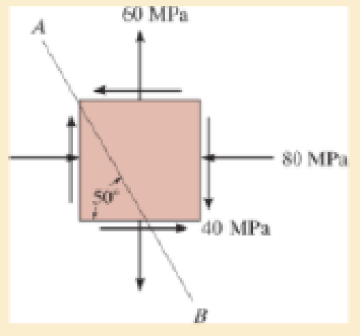
Solve Prob.9–7 using the stress transformation equations developed in Sec.9.2.
Expert Solution & Answer

Trending nowThis is a popular solution!

Students have asked these similar questions
69. A disc of 600 mm diameter and uniform thickness
is rotating at 3000 rpm. Calculate the maximum stress developed in the
disc.
If a hole of 100 mm dianmeter is drilled at the centre of the disc,
then determine maximum radial and hoop stresses developed. Take vs
0-28 and p = 7800 kg/m.
A hollow shaft with an outside diameter of 3.1 in. and an inside diameter of 2.8 in. is subjected to both a torque of T = 525 lb-ft and an
axial tension load of P = 6840 lb, as shown.
(a) Determine the principal stresses (0p1> 0p2) and the maximum shear stress Tmax at point H on the surface of the shaft.
(b) Show the stresses of part (a) and their directions in an appropriate sketch.
Answers:
%p1= i
1
op2=
Tmax
psi.
psi.
psi.
The cylinder for a hydraulic press has an inside diameter of 300 mm and an outside radius of 260 mm. Find the maximum shear stress in the cylinder for an internal pressure of 280 MPa.
Chapter 9 Solutions
Mechanics of Materials (10th Edition)
Ch. 9.3 - In each case, the state of stress x, y, xy...Ch. 9.3 - Given the state of stress shown on the element,...Ch. 9.3 - Determine the normal stress and shear stress...Ch. 9.3 - Determine the equivalent state of stress on an...Ch. 9.3 - Also, find the corresponding orientation of the...Ch. 9.3 - Determine the equivalent state of stress on an...Ch. 9.3 - Determine the maximum principal stress at point B.Ch. 9.3 - Determine the principal stress at point C.Ch. 9.3 - Prove that the sum of the normal stresses x + y =...Ch. 9.3 - Determine the stress components acting on the...
Ch. 9.3 - Determine the stress components acting on the...Ch. 9.3 - Determine the normal stress and shear stress...Ch. 9.3 - Determine the normal stress and shear stress...Ch. 9.3 - Determine the stress components acting on the...Ch. 9.3 - Determine the stress components acting on the...Ch. 9.3 - Solve Prob.97 using the stress transformation...Ch. 9.3 - Determine the stress components acting on the...Ch. 9.3 - Solve Prob.99 using the stress transformation...Ch. 9.3 - Determine the equivalent state of stress on an...Ch. 9.3 - Determine the equivalent slate of stress on an...Ch. 9.3 - Determine the stress components acting on the...Ch. 9.3 - Determine (a) the principal stresses and (b) the...Ch. 9.3 - The state of stress at a point is shown on the...Ch. 9.3 - Determine the equivalent state of stress on an...Ch. 9.3 - Determine the equivalent state of stress on an...Ch. 9.3 - A point on a thin plate is subjected to the two...Ch. 9.3 - Determine the equivalent state of stress on an...Ch. 9.3 - The stress along two planes at a point is...Ch. 9.3 - The stress acting on two planes at a point is...Ch. 9.3 - The state of stress at a point in a member is...Ch. 9.3 - The grains of wood in the board make an angle of...Ch. 9.3 - The wood beam is subjected to a load of 12 kN. If...Ch. 9.3 - The internal loadings at a section of the beam are...Ch. 9.3 - Solve Prob.925 for point B. 925. The internal...Ch. 9.3 - Solve Prob.925 for point C. 925. The internal...Ch. 9.3 - It is subjected to a torque of 12 kip in. and a...Ch. 9.3 - The bell crank is pinned at A and supported by a...Ch. 9.3 - The beam has a rectangular cross section and is...Ch. 9.3 - A paper tube is formed by rolling a cardboard...Ch. 9.3 - Solve Prob.931 for the normal stress acting...Ch. 9.3 - The 2-in.-diameter drive shaft AB on the...Ch. 9.3 - Determine the principal stresses in the...Ch. 9.3 - The internal loadings at a cross section through...Ch. 9.3 - The internal loadings at a cross section through...Ch. 9.3 - The shaft has a diameter d and is subjected to the...Ch. 9.3 - The steel pipe has an inner diameter of 2.75 in....Ch. 9.3 - Solve Prob.938 for point B, w1ich is located on...Ch. 9.3 - The wide-flange beam is subjected to the 50-kN...Ch. 9.3 - Solve Pro b. 9-40 for point B located on the web...Ch. 9.3 - The box beam is subjected to the 26-kN force that...Ch. 9.3 - Solve Prob.942 for point B. 942. The box beam is...Ch. 9.4 - Use Mohrs circle to determine the normal stress...Ch. 9.4 - Also, find the corresponding orientation of the...Ch. 9.4 - Draw Mohrs circle and determine the principal...Ch. 9.4 - Determine the principal stresses at a point on the...Ch. 9.4 - Determine the principal stresses at point A on the...Ch. 9.4 - Point A is just below the flange.Ch. 9.4 - Solve Prob.9-2 using Mohrs circle. 92. Determine...Ch. 9.4 - Solve Prob.93 using Mohrs circle. 93. Determine...Ch. 9.4 - Solve Prob.96 using Mohrs circle. 96. Determine...Ch. 9.4 - Solve Prob.911 using Mohrs circle. 911. Determine...Ch. 9.4 - Solve Prob.915 using Mohrs circle. 915. The state...Ch. 9.4 - Solve Prob.916 using Mohrs circle. 916. Determine...Ch. 9.4 - Mohrs circle for the state of stress is shown in...Ch. 9.4 - Determine (a) the principal stresses and (b) the...Ch. 9.4 - Determine (a) the principal stresses and (b) the...Ch. 9.4 - Determine the equivalent state of stress if an...Ch. 9.4 - Draw Mohrs circle that describes each of the...Ch. 9.4 - Draw Mohrs circle trial describes each of the...Ch. 9.4 - Determine (a) the principal stresses and (b) the...Ch. 9.4 - Determine (a) the principal stresses and (b) the...Ch. 9.4 - Determine (a) the principal stresses and (b) the...Ch. 9.4 - Determine (a) the principal stresses and (b) the...Ch. 9.4 - Determine (a) the principal stresses and (b) the...Ch. 9.4 - Draw Mohrs circle that describes each of the...Ch. 9.4 - The grains of wood in the board make an angle of...Ch. 9.4 - The post is fixed supported at its base and a...Ch. 9.4 - Determine the principal stresses, the maximum...Ch. 9.4 - The thin-walled pipe has an inner diameter of 0.5...Ch. 9.4 - The frame supports the triangular distributed load...Ch. 9.4 - The frame supports the triangular distributed load...Ch. 9.4 - The rotor shaft of the helicopter is subjected to...Ch. 9.4 - The pedal crank for a bicycle has the cross...Ch. 9.4 - A spherical pressure vessel has an inner radius of...Ch. 9.4 - The cylindrical pressure vessel has an inner...Ch. 9.4 - Determine the normal and shear stresses at point D...Ch. 9.4 - Determine the principal stress at point D, Which...Ch. 9.4 - If the box wrench is subjected to the 50 lb force,...Ch. 9.4 - If the box wrench is subjected to the 50-lb force,...Ch. 9.4 - The post is fixed supported at its base and the...Ch. 9.5 - Draw the three Mohrs circles that describe each of...Ch. 9.5 - Draw the three Mohrs circles that describe the...Ch. 9.5 - Draw the three Mohrs circles that describe the...Ch. 9.5 - Determine the principal stresses and the absolute...Ch. 9.5 - Determine the principal stresses and the absolute...Ch. 9.5 - Determine the principal stresses and the absolute...Ch. 9.5 - Determine the principal stresses and the absolute...Ch. 9.5 - The solid shaft is subjected to a torque, bending...Ch. 9.5 - The frame is subjected to a horizontal force and...Ch. 9.5 - The bolt is fixed to its support at C. If a force...Ch. 9.5 - The bolt is fixed to its support at C. If a force...Ch. 9 - Prob. 9.1RPCh. 9 - The steel pipe has an inner diameter of 2.75 in....Ch. 9 - Determine the equivalent state of stress If an...Ch. 9 - The crane is used to support the 350-lb load....Ch. 9 - Determine the equivalent state of stress on an...Ch. 9 - The propeller shaft of the tugboat is subjected to...Ch. 9 - Determine the principal stresses in the box beam...Ch. 9 - Determine (a) the principal stresses and (b) the...Ch. 9 - Determine the stress components acting on the...
Knowledge Booster


Learn more about
Need a deep-dive on the concept behind this application? Look no further. Learn more about this topic, mechanical-engineering and related others by exploring similar questions and additional content below.Similar questions
- Repeat the previous problem using ? = 50° and stresses on the rotated element: sy1= 70 MPa, ??y1=-82 MPa, and tx1y1=-35 MPa.arrow_forward5. A thick-walled tube with closed ends has inner and outer radii of 30 and 50 mm, respectively. It contains air at 160 MPa and is also subjected to a external torque of 30 KN*m. The materials is AISI steel with yield strength of 1378 MPa. What are the safety factors against yielding at R =30 mm, 35 mm, 40 mm, 45 mm, and 50 mm. Use the stresses for thick walled cylindrical vessel. Use the maximum distortion energy theory. pr? pr pr} 2TRarrow_forwardA pipe carrying steam at 3.0 MPa has an outside diameter of 450 mm and a wall thickness of 10 mm. A gasket is inserted between the flange at one end of the pipe and a flat plate used to cap the end. How many 25 mm diameter bolts must be used to hold the cap on if the allowable stress in the bolts is 90 MPa of which 50 MPa is the initial stress? What circumferential stress is developed in the pipe?arrow_forward
- A machinery uses a helical tension spring with wire diameter of 3 mm and coil outside diameter of 35 mm. The spring has 9 total coils. The design shear stress is 500 MPa and the modulus of rigidity is 82 GPa. Determine the force that causes the body of the spring to its shear stress in N. Consider ground ends.arrow_forwardThe solid shaft shown below is in equilibrium, supported at two bearings A and B. The pulleys C and D have diameters in the ratio 3:2. T₁ = 1000 N, T₂ = 500 N and T3 = 1500 N. The diameter of the shaft is 50 mm and yield strength sy 400 MPa. The bearings do not exert any moments or axial forces on = the shaft. a. Determine the principal stresses corresponding to maximum bending and torsional shear stresses. Ignore transverse shear stresses due to bending. C A H 0.3 m 0.5 m 0.2 m B T₁ 30° T3 60° TAarrow_forwardA compound cylinder is made by shrinking a jacket with an outer diameter of 200 mm on a hollow cylinder with diameter of 100 mm and 150 mm. When the compound cylinder is subjected to an internal pressure of 35MNm-2, the maximum circumferential stress in both cylinders is the same. Calculate the maximum stress developed at the internal diameter of the jacket.arrow_forward
- Two blocks joined by a single pin are subjected to a pulling force of P = 250 Ib. The pin has a diameter of 0.25 in and the dimensions of the blocks with respect to the figure below are listed below. a = 2.42 in b = 1.52 in C = 1.5 in ti = 0.89 in t2 = 1.2 in Note that the dimensions b and c represent the distance from the edge of the block to the middle of the pin t, 1 a Vinter201920-Engr220-001/images/9de8f780-b478-3fb6-91f7-bd1015381538_fafc4bb4-e5d Image is not drawn to scale.arrow_forwardestion 11 62.5 mm Кey 55° The cast iron block with cross-sectional dimensions of 62.5 mm by 62.5 mm consists of two pieces. The pieces are prevented from sliding along the 55° inclined joint by the steel key, which is 62.5 mm long. The working stresses are 275 MPa for cast iron in bearing and 345 MPa for the key in shear. If the block is loaded with P = 256 kN, calculate the required dimension "h" of the key. Write your final answer in 2 decimal places with the unit of mm.arrow_forwardA solid disc rotating with maximum velocity V and having Poisson's ratio is u, then the maximum tangential and radial stress developed in the disc is At the middle of the radius At the outer surface of the disc At the centre of the disc Nowhere is maximumarrow_forward
- A stepped steel shaft is fixed to a wall at one end and subjected to torsion and axial loading as shown. The torque T=100 kip-in. Find the state of stress for two locations on the shaft: one between A and B and one between B and C. For each location, calculate the principal stresses and directions (i.e. the value of the angle 0). Draw the state of stress aligned with the principal directions. 12 in. 15 in. 2T A 6 in. B 4 in. C 125 kiparrow_forwardA hollow shaft with an outside diameter of 3.2 in. and an inside diameter of 2.6 in. is subjected to both a torque of T = 614 lb-ft and an axial tension load of P = 7410 lb, as shown. (a) Determine the principal stresses (σp1 > Op2) and the maximum shear stress Tmax at point H on the surface of the shaft. (b) Show the stresses of part (a) and their directions in an appropriate sketch. H (1) I X Barrow_forwardA 100mm diameter steel shaft is loaded as indicated in the figure. Determine the angle of twist of pulley D with respect to pulley A. What are the constant stresses in the three sections of the shaft?arrow_forward
arrow_back_ios
SEE MORE QUESTIONS
arrow_forward_ios
Recommended textbooks for you
 Mechanics of Materials (MindTap Course List)Mechanical EngineeringISBN:9781337093347Author:Barry J. Goodno, James M. GerePublisher:Cengage Learning
Mechanics of Materials (MindTap Course List)
Mechanical Engineering
ISBN:9781337093347
Author:Barry J. Goodno, James M. Gere
Publisher:Cengage Learning
Understanding Stress Transformation and Mohr's Circle; Author: The Efficient Engineer;https://www.youtube.com/watch?v=_DH3546mSCM;License: Standard youtube license