
Concept explainers
(a)
Use LFRD method to select the
Answer to Problem 9.5.1P
Explanation of Solution
Given:
Thickness of slab, t = 4.5 inches, spacing = 6.5 ft, span length, L = 36 feet, yield stress = 50 Ksi
Construction load = 20 psf, and live load = 175 psf.
The value of
Concept Used:
Calculation:
Using LRFD method, we have
To select the suitable W 16 shape as follows:
Calculate the loads on the beam as follows:
After curing we have,
Where,
between two adjacent beams.
The dead load on the beam after the concrete has cured is:
Where,
Neglecting the beam weight and check for it later.
Calculate the live load on the beam using the following equation:
Where,
Calculate the factored uniformly distributed load after curing has completed by the following formula:
Where,
Substitute the values, we get
Calculate the bending moment on the beam;
Where,
Let’s try a 16-inch deep beam.
Select a shape with the limiting self-weight given by the following formula:
Where, t is the thickness of the concrete slab, d is the depth of the steel beam, a is the distance of the neutral axis from the top,
Estimating weight per unit foot of the steel beam as:
Let’s try for W 16 X 31 and note the properties and dimensions from the Manual.
Calculate the strength of the section as following below:
Where, the compressive force is C, the compressive force of concrete is
Calculate the compressive force in steel as follows:
Where, the area of steel section is
Get the value of
Calculate the compressive force in concrete as following:
Where, b is the width of the concrete slab, t is the thickness of the concrete beam and
The effective flange width is as follows:
Substitute the values in the above equation, we get
Therefore, the compressive force is as follows:
Therefore, the plastic neutral axis lies in the slab.
Calculate the tensile force (T) and compressive force (C) and the position of plastic neutral axis from the top of concrete slab by following formula:
Compute the flexural strength as:
Where,
neutral axis.
Compute the value of Y as following below:
Substitute the values, we get
Calculate the design strength of the section as follows:
Where,
Substitute the values, we get
The flexural strength of the beam after curing is given as:
Where,
Comparing the values of
Thus, the beam is satisfactory in bending after the curing of concrete is complete.
Check for beam weight.
Where,
Substitute the values, we get
Calculate the maximum bending moment on the beam;
Where,
Check the flexural strength of the beam.
Compare the maximum bending moment and the nominal flexural strength
Comparing the values of
Thus, the section is safe in flexure including its self-weight.
Check for the shear:
Checking the value of nominal value of shear strength of
Where,
The maximum shear force is as following for the above conditions:
Substitute the values, we have
Now comparing the two we have
Therefore, the beam is safe in shear and we can use
Calculate the factored uniformly distributed load after curing has completed by following formula:
Load before curing:
Calculate the self-weight of the slab to be allowed by a single beam as
Where,
The dead load on the beam before the concrete has cured
Where, w is the self-weight of the beam
Substitute the values, we have
Now, calculate the live load on the beam as follows
Where the construction load on the slab is
The uniformly distributed factored load can be found as
Where,
Substitute the values in the above equation, we have
Calculate the maximum bending moment on the beam.
Where,
Check the value of the nominal flexural strength of W- sections from the Manual:
Flexural strength of the beam before curing is given as follows:
Where,
Comparing the values of
Thus, the beam is satisfactory before the curing of concrete is complete.
Therefore, W 16 X 31 is satisfactory to use.
Conclusion:
Therefore,
(b)
Use ASD method to select the
Answer to Problem 9.5.1P
Explanation of Solution
Calculation:
Applying Allowable stress design:
Select appropriate W 16 shape
Calculate the loads on the beam as follows:
Before curing
Calculate the self-weight of the slab to be allowed by a single beam as follows:
Where,
between two adjacent beams.
The dead load on the beam after the concrete has cured is:
Where,
Neglecting the beam weight and check for it later.
Calculate the live load on the beam using the following equation:
Where,
Calculate the allowable uniformly distributed load as follows:
Substitute the values as follows
Calculate the bending moment on the beam;
Where,
Let’s try a 16-inch deep beam.
Select a shape with the limiting self-weight given by the following formula:
Where, t is the thickness of the concrete slab, d is the depth of the steel beam, a is the distance of the neutral axis from the top,
Estimating weight per unit foot of the steel beam as:
Let’s try for W 16 X 31 and note the properties and dimensions from the Manual.
Calculate the strength of the section as following below:
Where, the compressive force is C, the compressive force of concrete is
Calculate the compressive force in steel as follows:
Where, the area of steel section is
Get the value of
Calculate the compressive force in concrete as following:
Where, b is the width of the concrete slab, t is the thickness of the concrete beam and
The effective flange width is as follows;
Substitute the values in the above equation, we get
Therefore, the compressive force is as follows:
Therefore, the plastic neutral axis lies in the slab.
Calculate the tensile force (T) and compressive force (C) and the position of plastic neutral axis from the top of concrete slab by following formula:
Compute the flexural strength as:
Where,
neutral axis.
Compute the value of Y as following below:
Substitute the values, we get
Calculate the design strength of the section as follows:
Where,
Substitute the values, we get
Check the nominal value of the flexural strength of W- sections from the manual.
Where,
Comparing the values, we get
Thus, the beam is satisfactory after curing of concrete has completed.
Check for beam weight
Calculating the max bending mo0ment by busing the following formula:
Substitute the values as follows:
Now, checking the flexural strength with the beam taken into consideration:
Compare the maximum bending moment and the nominal flexural strength
Comparing the values of
Thus, the section is safe in flexure including its self-weight.
Check for the shear:
Checking the value of nominal value of shear strength of
Where,
The maximum shear force is as following for the above conditions:
Substitute the values, we have
Now comparing the two we have
Therefore, the beam is safe in shear.
Loading before curing:
Calculate the self-weight of the slab to be allowed by a single beam as follows:
Where,
between two adjacent beams.
The dead load on the beam before the concrete has cured
Where, w is the self-weight of the beam
Substitute the values, we have
Now, calculate the live load on the beam as follows
Where the construction load on the slab is
The uniformly distributed factored load can be found as
Where,
Substitute the values in the above equation, we have
Calculate the maximum bending moment on the beam;
Where,
Check the value of the nominal flexural strength of W- sections from the Manual:
Flexural strength of the beam before curing is given as follows:
Where,
Comparing the values of
Thus, the beam is satisfactory before the curing of concrete is complete.
Conclusion:
Therefore,
(c)
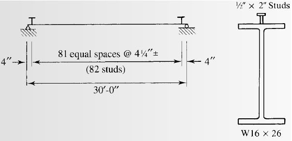
Selecting the stud anchors for the given section.
Answer to Problem 9.5.1P
we will use
Explanation of Solution
Calculation:
We have to check whether the studs satisfy the ASIC specifications.
From AISC specifications the maximum stud diameter will be equal to
Where,
Substitute the values in the equation, we get
Try for,
The area of stud using the following equation as follows:
Where, the diameter of the stud is d.
Substitute
We have the modulus of elasticity of concrete as follows:
Where, the modulus of elasticity of concrete is
unit weight of concrete is
the 28-day compressive strength of concrete is
Substitute
Calculating the shear strength of stud with the following formula:
Substitute the values, we get
Now, the upper limit of the shear strength is as follows:
As, the calculated value is less than the upper limit given by AISC, take the shear strength as:
The number of studs required for the half beam are as follows:
Substitute the values, we have
The number of studs required are as follows:
Substitute the values, we have
Calculate the spacing of the studs as following:
The minimum longitudinal spacing for the studs will be as follows:
Where, the minimum longitudinal spacing for the studs is
Substitute the values, we have
The minimum transversal spacing for the studs will be as follows:
Where, the minimum transversal spacing for the studs is
Substitute the values, we have
The maximum longitudinal spacing for the studs will be as follows:
Where, the maximum longitudinal spacing for the studs is
Substitute the values, we have
Therefore, the upper limit of the spacing is 36 inches.
Calculating the spacing for a stud at each section by the following formula:
Where, S is the spacing required
Conclusion:
Therefore, we will use
Want to see more full solutions like this?
Chapter 9 Solutions
Steel Design (Activate Learning with these NEW titles from Engineering!)


- O Find the ultimate moment of resistance for the rectangular section reinforced as shown below. material strengths: Concrete Reinforcement Width of section Reinforcement fcu:= 30-MPa fy:= 450-MPa b:= 280-mm d:= 510-mm A, 2410-mm d':= 50-mm A's:= 628-mm² b A', d'arrow_forwardProblem Solving: A rectangular beam has dimensions of 250 mm by 625 mm with an effective depth (distance from extreme fiber in tension to the centroid of the reinforcing bars) of 575 mm and is reinforced with three 25 mmp. The concrete cylinder strength f.' = 27.6 MPa and the tensile strength in bending (modulus of rupture) is 3.28 MPa. The yield point of the steel is 414.7 MPa. The beam carries a bending moment of 61 kN.m. E_ = 200000 MPa. E_ = 4700,f. Using the transformed area method, determine the stress in the extreme fiber in compression.arrow_forwardReferenced concrete When designing the same bim Why is the load in the case of moment greater than the load in the case of shear?arrow_forward
- Find the ultimate moment of resistance for the rectangular section reinforced as shown below. material strengths: Concrete Reinforcement Width of section Reinforcement fcu= 30-MPa fy:= 450-MPa b:= 280 mm d:= 510 mm d':= 50-mm 2 A, 2410-mm A's:= 628-mm 2 b A', Hi Asarrow_forwardProblem 1. The composite beam shown below carries a cantilevered load of 10 kN. The beam consists of one 30 x 124 mm plate and four 12 x 50 mm plates. They are pinned together at 120 mm intervals with round pins. The pin material has a shear strength of 159 MPa. Compute the minimum acceptable diameter for the pins. O O O O O O O -0 O 0- O 1000 mm Do O -120 mm (typ) O O O P = 10 KN 30 x 124 mm 12 x 50 mm (typ)arrow_forward2. Determine if the composite beam pictured below is adequate for this application (this includes bending, shear, deflection and shear stud limit states). The dead load for this beam is 10 psf plus the weight of the deck, which is made from normal weight concrete. I 5" 5" Normal weight slab fc=4000 psi W24x94 Span length = 30' Service Live Load = 100 psf 3/4" Diameter Shear Connectors 8' o.c. typical Fu=60 ksi (shear connectors)arrow_forward
- A beam having a width of 500 mm and a total depth of 800mm is reinforced with 6-32mm dia bars Compressive strength of concrete is 28 MPa and yield strength of reinforcing bars is 420MPaa) depth of the compression blockb) strain in the tension reinforcementc) moment reduction factorarrow_forwardPLEASE WRITE YOUR COMPLETE SOLUTION AND BOX THE FINALS ANSWERS. THANK YOU. A composite bar consists of steel segments with different cross-sections are rigidly fastened as shown. Axial loads are applied at the positions indicated. The stress must not exceed 116 MPa in tension, and 77 MPa in compression. Determine the following: (a) the safe value of P to the nearest safe 1 kN, if the diameter of segment 1 is 100 mm; (b) the required side length of the equilateral triangle segment 2 to the nearest safe 25 mm; and (c) the required side length of the regular pentagon segment 3 to the nearest safe 25 mm.arrow_forward1 Situation 19. A composite beam shown is subjected to a bending moment of 500 kN-m. Determine the maximum flexural stress; 300 VIEW INNOVATIONS 200 200 100 55. Experienced by the steel 56. Experienced by the aluminum A. 0.03 B. 25.24 57. Experienced by the brass A. 25.24 B. 37.86 REVIEW I EW INNOVATIONS Steel, E=200 GPa Aluminum, E=70 GPa Brass, E-105 GPa wwwww C. 48.2 D. 72.11 C. 16.8 C. 16.8 D. 11.21 VIEW INNOVATIONS REVIEW INNOVATIONS REVIEW ISarrow_forward
- Find of the given area, relative to the given x-y axis, using the composite method, assuming r = 72 mm and h = 80 mm. Find y Parabola Vertex h 48 mmarrow_forwardA composite bar consists of an aluminum section rigidly fastened between a bronze section and steel section. Axial loads are applied at the positions indicated. Determine the stress in each section.arrow_forwardEstimate the transverse tensile strength of the concrete in Problem 12.6.arrow_forward
 Steel Design (Activate Learning with these NEW ti...Civil EngineeringISBN:9781337094740Author:Segui, William T.Publisher:Cengage Learning
 Materials Science And Engineering PropertiesCivil EngineeringISBN:9781111988609Author:Charles GilmorePublisher:Cengage Learning