
Videos
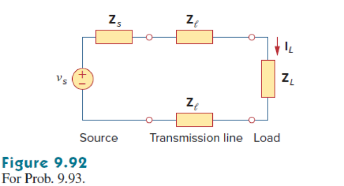
A power transmission system is modeled as shown in Fig. 9.92. Given the source voltage and circuit elements
Want to see the full answer?
Check out a sample textbook solution
Chapter 9 Solutions
Fundamentals of Electric Circuits
Additional Engineering Textbook Solutions
Introductory Circuit Analysis (13th Edition)
Electric Circuits (10th Edition)
Microelectronics: Circuit Analysis and Design
Basic Engineering Circuit Analysis
Programmable Logic Controllers
Electric machinery fundamentals


- total Impedance - for the circuit shown assume that the Voltage Sowee angular frequency is W = 5000 rad/s Calculate the total circuit impedance ZT as Viewed from the voltage Source terminals. Report only the magnitud of the total impedance in [2] V @ A Sn www 2mH 72² 10 μFarrow_forwardThe phasor current through an impedance Z and the voltage across it are given as: V = 4 VL 2° 1= 3.4 AL-65° V ? Z = ? This impedance is: Z = Important: Your answers must be rounded to 1 decimal place (example: 13.3L 22.7°). Important: You must enter both fields to get a grade.arrow_forwardConsider the network depicted in the following figure, and determine the eqdivalent impedance seen looking into the open terminals if w = 15rad/s 2 mF 20 0 250 55 0 Oa. 12.482 - J 3.864 0 Ob. 8.482- J7.864 0 Oc. 14.482 - J 1864 0 Oo. 10.482 - J 5.864 0arrow_forward
- Find the load impedance (Xcı) for the network in figure for maximum power to the load, and find the maximum power to the load. (ZL = 1+j1) 40 E = 60 V 60° Xc, 60 R 10 Ωarrow_forward7. Find all branch currents in the circuit below and the equivalent impedance of the general circuit seen from the voltage source with the help of phasors. V(t)=10 e^jwt V, w=10^4 rad / s.arrow_forwardIf in each branch of a star circuit, it has impedance Z/V3, then each circuit of its equivalent delta branch will have Select one: a. 2* Z/3 b. None of these c. Z/V3 d. Z*V3arrow_forward
- 9. The reactive power for purely capacitive load can be represented in phasor diagram b) 10. If the angle of the load impedance Z is 37°, then the angle of the complex power S is a) 530 b) can't be determined c) - 370 d) 370arrow_forwardoY l. l. A docs.google.com/forms/d/e. بيانات الطالب Q1(6*1)/For the circuit shown in the figure :below, using nodal analysis to find 8 S 2A 4 4S 13 V نقطة واحدة The voltage source which is :become as a super node is 2Vo 13V 2Vo and 13V no super node The final voltage eauation of the II S wwH wwarrow_forwardA resistor'R' with resistance value of 24 ohm, an inductor 'L' with inductance 20mH, and a capacitor 'C' with capacitance 50 micro Farrad are connected in series with a AC voltage v(t) where v(t) = 50 cos (2 vt + 30 degrees) v. Determine the current i(t) and total impedance if the frequency f is i. 60 Hz ii. 400Hzarrow_forward
- Asiacell 9:11 O %01 令.l .ll Asiacell HOMEWORK An A.C. bridge has the following parameters Arm (AB): R1= 1KO, C1 = 1µF, Arm (AD): R2 = 3KO, L2 = 1mH, Arm (BC): R3= 2KO, Arm (DC) unknown cimpedance (Zx) The source is connected between (AC) the voltage is 10V with frequency is 1KHZ What would the resonant frequency of a Wien bridge circuit be if the resistors are 400 K2 and .capacitors are 0.4 µF An AC bridge is balanced at 2KHZ with the following components in each arm: Arm AB=10KO, Arm BC=100µF in series with 100KO, Arm AD=50KO Find the unknown impendence R+ X in the am DC, if the detector is between BD 10arrow_forwardt& Evalu EENGBO0 MIDTERM EXAM SPF empt 1980628tcmid%3D11616 Q Gasgle Google Trarlat Youulube rse Given the circuit below and the associated set of voltages and currents, the reactive Power developed by -j160 capacitor is ut of + V1 10 V, 39 I, -j16 02 V, = 150 /0° V I, = (-26- j52) A I, = (-2 + j6) A I = (-24- j58) A V = (78 - j104) V V2 = (72 + j104) V V3 = (150 - j130) V Capyh Pn on Ha Select one: O a. 320 VAR • b. 3200 VAR O c. None of these O d. 220 VAR Clear my choicearrow_forward$ R 96 5 T O + Q Search G B The angle of the total impedance is....... degrees ZT-> 6 Y H Z₁ www R = 60 N & U ** 4+ 8 M 1 TWO 3 Complement... EL-204-D01_2023_1... book.pdf Adigital-fundamental... C K 9 Z₂ voo H6 X₁ = = 10 Ω _ Xc = 12 Ω 2 O alt M11 O الالك P : 7 ctrl ? { [ / + (( = Z3 4 "brt sc } 1 and 7 home 9:33 PM 11/22/2023 Other fa 4 2 1 endarrow_forward
 Introductory Circuit Analysis (13th Edition)Electrical EngineeringISBN:9780133923605Author:Robert L. BoylestadPublisher:PEARSON
 Delmar's Standard Textbook Of ElectricityElectrical EngineeringISBN:9781337900348Author:Stephen L. HermanPublisher:Cengage Learning
 Programmable Logic ControllersElectrical EngineeringISBN:9780073373843Author:Frank D. PetruzellaPublisher:McGraw-Hill Education
 Fundamentals of Electric CircuitsElectrical EngineeringISBN:9780078028229Author:Charles K Alexander, Matthew SadikuPublisher:McGraw-Hill Education
 Electric Circuits. (11th Edition)Electrical EngineeringISBN:9780134746968Author:James W. Nilsson, Susan RiedelPublisher:PEARSON
 Engineering ElectromagneticsElectrical EngineeringISBN:9780078028151Author:Hayt, William H. (william Hart), Jr, BUCK, John A.Publisher:Mcgraw-hill Education,