
Videos
Find v(t) in the RLC circuit of Fig. 9.48.
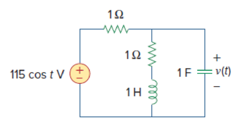
Figure 9.48
Find the value the voltage
Answer to Problem 41P
The value of the voltage
Explanation of Solution
Given date:
Refer to Figure 9.48 in the textbook.
Formula used:
Write the expression to convert the time domain expression into phasor domain.
Here,
A is the magnitude,
t is the time, and
Write the expression to calculate the total phasor current.
Here,
Write the expression to calculate the impedance of the passive elements resistor, inductor and capacitor.
Here,
Calculation:
The given RLC circuit is redrawn as Figure 1.
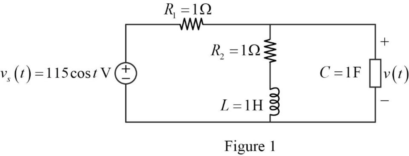
Refer to Figure 1, the source voltage is,
Here, angular frequency
Use the equation (1) to express the above equation in phasor form.
Substitute
Substitute
Substitute
Substitute
The Figure 1 is redrawn as impedance circuit in the following Figure 2.
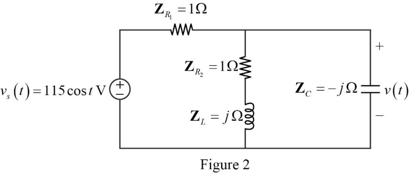
Refer to Figure 2, the series combination of the impedances
Write the expression to calculate the equivalent impedance 1 for the parallel combination as follows.
Here,
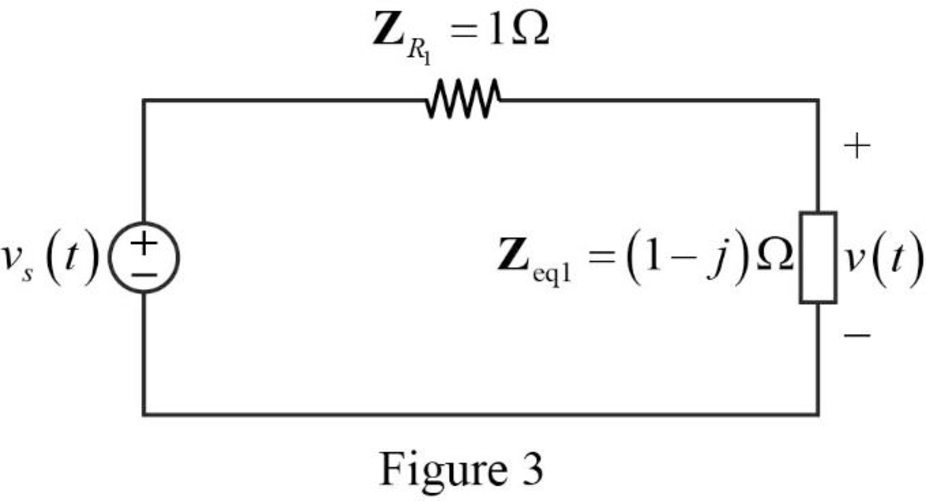
Substitute
The reduced circuit of the Figure 2 is drawn as Figure 3.
Refer to Figure 2, the impedances
Write the expression to calculate the equivalent capacitance for the series connected impedances
Here,
Substitute
The reduced circuit of the Figure 3 is drawn as Figure 4.
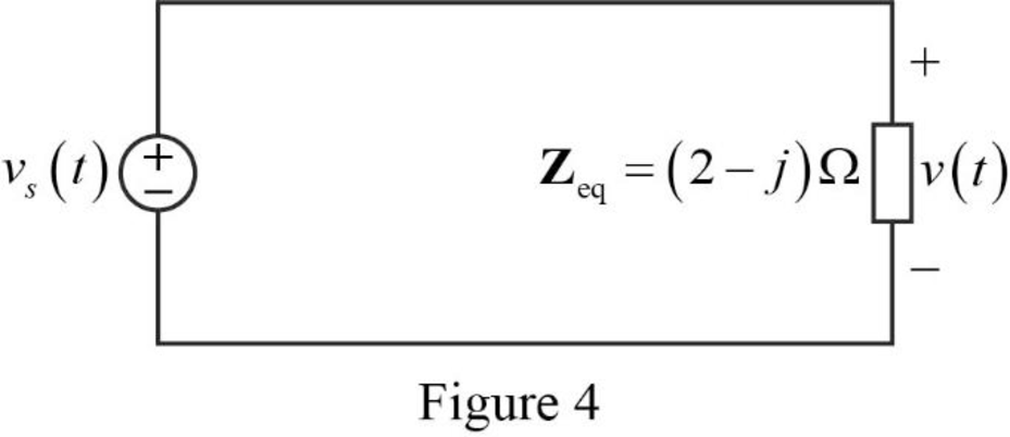
Substitute
Refer to Figure 2, the current through the capacitor is expressed as,
Refer to Figure 2, the voltage across the capacitor is expressed as,
Substitute
Substitute
Use the equation (1) to express the above equation in time domain form.
Substitute
Conclusion:
Thus, the value of the voltage
Want to see more full solutions like this?
Chapter 9 Solutions
Fundamentals of Electric Circuits
Additional Engineering Textbook Solutions
Electric machinery fundamentals
Microelectronics: Circuit Analysis and Design
Programmable Logic Controllers
Electrical Engineering: Principles & Applications (7th Edition)
Basic Engineering Circuit Analysis
Electric Circuits (10th Edition)


- The ac bridge shown in Fig. 9.84 is known as a Maxwell bridge and is used for accurate measurement of inductance and resistance of a coil in terms of a standard capacitance C.. Show that when the bridge is balanced, R2 R3 R₁ Lx = R₂R3Cs and Rx = 1.6 ΚΩ, Find Lx and R, for R₁ = 40 kN, R₂ R3 = 4 kn, and C₂ = 0.45 µF. R₁ R3 Cs R₂ AC meter R₂ ellarrow_forwardGiven That: Is=0.0098, R1=60000, R2=6000 0, L=16 H, C=2 F, The circuit shown below under dc conditions find the following: L ell Is R1 R2 the current in L The voltage across capacitorarrow_forwardUse phasor approach to determine the current i(t) in a circuit describe by the integrodifferential equation below di 5+ 3i(t) +7 i dt i dt = 20 sin(4t + 80°) dtarrow_forward
- Consider the circuit in the following figure. Under dc conditions, find: (a) i, gc, and is. (b) the energy stored in the capacitor and inductor. 12 V 192 wwww "C 492 1 F 592 2 H ell ILarrow_forwardProblem 3: Transients in linear circuits- E-60 V R=102 L=10mH R:=R=100 R1 Ry Find: the current: İL(t)=? Rsarrow_forwardIn the network shown in figure, the switch closes at t=0. The capacitor is initially uncharged find the ve(t) and ic(t). 10V- 9kQ ww 4kQ 1kQ 3μFarrow_forward
- (b) A circuit network has two capacitors C1, and C2, that are connected in series and are supplied by a 12V voltage source. If C1 = 470µF and C2=220µF, sketch the circuit diagram and find the voltage across each of the capacitors:- (6) As a fresh engineer working with a mobile phone company, you have been tasked %3Darrow_forwardQ4: Sketch the root locus of the system, showing all steps in details K G(s)H(s) s4+ 5s3+8s2+6sarrow_forwardUse Euler's formula to simplify: cos(1+i). ..arrow_forward
- 2. Given that: C1 = 10.00F C3 = 6.00F, q2=25.00 C, Solve for the following: V1, V2, q1, C2, V3, q3, Ctotal, qtotal (3 capacitors)arrow_forwardgiven the circuit below , find and plot the current ix(t) for t>0s A=3A resistors=2 ohms each anc capacitor=1/4F voltage source is 3ix. solve in great detail.arrow_forward1. An RLC circuit consists of three elements: a resistor (R), and inductor (L) and a capacitor (C), as shown. By Kirchhoff's voltage rule, the algebraic sum of the voltage drops around a closed circuit is zero. Resistor Inductor Capacitor Ldi dt iR mell Thus, iR +L di +9 = 0 where i = current in amperes (A), R= resistance in ohms (2), L = inductance in henrys (H), q = charge in coulombs (C) and C = capacitance in farads (F). di (Note: Solve for - dt in the equation above) Also, the current is related to the charge given by dq dt (a) If the initial values are i(0) = 0 and q(0) = 1.5 C, use Euler's method to solve this pair of differential equations from t = 0 to t = 0.01 s using a step size of At = 0.01 s. Use R= 2002, L= 5 H, and C = 10 F. The table is similar to this: i (b) Plot i vs. t and q vs. t curves using google sheet or excel on a single chart.arrow_forward
 Introductory Circuit Analysis (13th Edition)Electrical EngineeringISBN:9780133923605Author:Robert L. BoylestadPublisher:PEARSON
 Delmar's Standard Textbook Of ElectricityElectrical EngineeringISBN:9781337900348Author:Stephen L. HermanPublisher:Cengage Learning
 Programmable Logic ControllersElectrical EngineeringISBN:9780073373843Author:Frank D. PetruzellaPublisher:McGraw-Hill Education
 Fundamentals of Electric CircuitsElectrical EngineeringISBN:9780078028229Author:Charles K Alexander, Matthew SadikuPublisher:McGraw-Hill Education
 Electric Circuits. (11th Edition)Electrical EngineeringISBN:9780134746968Author:James W. Nilsson, Susan RiedelPublisher:PEARSON
 Engineering ElectromagneticsElectrical EngineeringISBN:9780078028151Author:Hayt, William H. (william Hart), Jr, BUCK, John A.Publisher:Mcgraw-hill Education,