
Theory and Design for Mechanical Measurements
6th Edition
ISBN: 9781118881279
Author: Richard S. Figliola, Donald E. Beasley
Publisher: WILEY
expand_more
expand_more
format_list_bulleted
Videos
Textbook Question
Chapter 9, Problem 9.25P
The pressure transmission line response equation of Equation 9.23 can also be derived by considering the forces acting on a fluid element within the connecting tubing (12). Develop a model for the system measured pressure response based on an applied pressure force, shear resistance force, and restoring compliance related force through Newton’s momentum (second law) principles. Refer to Figure 9.35.
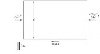
Figure 9.35 Freebody diagram on a fluid element (x-direction) for Problem 9.25.
Expert Solution & Answer
Want to see the full answer?
Check out a sample textbook solution
Students have asked these similar questions
Q5/ A ring has a diameter of 21 cm and a cross-section area of 10 cm2. The
ring is made up of semicircular sections of cast iron and cast steel, with
each joint having a reluctance equal to an air-gap of 0.2 mm. find the
ampere-turns required to produce a flux of 8x10⁻⁴ Wb. The Neglect
fringing and leakage effects.
Cast Iron
0.2 mm
21'Cms
0.2 mm
Cast Steel
.
Problem 9-4: The pressure fluctuations in a pipe filled with air at 20°C at about
1 atm is to be measured using a static wall tap, rigid connecting tubing, and a
diaphragm pressure transducer. The transducer has a natural frequency of 100000 Hz
For a tap and tubing diameter of 3.5 mm, a tube length of 0.25 m, and a transducer
dead volume of 1600 mm³, estimate the resonance frequency of the system. What is
the maximum frequency that this system can measure with no more than a 10%
dynamic error? Plot the frequency response of the system.
3. Microfluidic channels will need to be fabricated on a key micro-scale sensor used by aerospace
industries. Before running machining tests and analyzing machined quality, preliminary efforts are needed
to evaluate selected materials and factors affecting machining process¹. Three material candidates have
been selected, including 422SS (stainless steel), IN718 (nickel alloy), and Ti64 (titanium alloy) with their
measured tensile properties and equation of true stress-true strain relationship used listed below. Tref25°C.
Specifically, three factors will need to be evaluated, including different materials, temperature, and size
effect. Please calculate true stress values for true strain ranging between 0-3 for each case listed below.
Material
A (MPa)
& (S-¹)
Tm (°C)
870
0.01
1520
422SS (Peyre et al., 2007)
IN718 (Kobayashi et al., 2008)
Ti64 (Umbrello, 2008)
980
1
1300
782.7
1E-5
1660
Material
422SS (CINDAS, 2011)
IN718 (Davis, 1997)
Ti64 (Fukuhara and Sanpei, 1993)
0 =
X
G (GPa)
1+
B…
Chapter 9 Solutions
Theory and Design for Mechanical Measurements
Ch. 9 - Prob. 9.1PCh. 9 - 9.2 State the following pressures as absolute...Ch. 9 - A water-filled manometer is used to measure the...Ch. 9 - Prob. 9.4PCh. 9 - 9.5 The pressure differential across an orifice...Ch. 9 - Show that the static sensitivity of an inclined...Ch. 9 - Prob. 9.7PCh. 9 - Show that the instrument (systematic) uncertainty...Ch. 9 - A strain gauge, diaphragm pressure transducer...Ch. 9 - Select a practical fluid to use in a manometer to...
Ch. 9 - An air pressure over the 200- to 400-N/m2 range is...Ch. 9 - Calculate the design-stage uncertainty in...Ch. 9 - The pressure drop across a valve through which air...Ch. 9 - Estimate the sensitivity (pF/mm) of a capacitance...Ch. 9 - A diaphragm pressure transducer is calibrated...Ch. 9 - A diaphragm pressure transducer is coupled with a...Ch. 9 - Prob. 9.17PCh. 9 - A 2.0 mm thick circular steel diaphragm (Em = 200...Ch. 9 - Estimate the differential pressure limit for a...Ch. 9 - The pressure fluctuations in a pipe filled with...Ch. 9 - What is the sensitivity of a pitot-static tube...Ch. 9 - A pitot-static pressure probe inserted within a...Ch. 9 - A tall pitot-static tube is mounted through and...Ch. 9 - The pressure transmission line response equation...Ch. 9 - Prob. 9.26PCh. 9 - Prob. 9.28PCh. 9 - Compare the inertance of water in a 0.2-m-long...Ch. 9 - The output from a resting healthy human adult...Ch. 9 - Prob. 9.31PCh. 9 - A pressure drop of 213 Pa is measured between two...Ch. 9 - Wall pressure taps (e.g., Figs. 9.19 and 9.21) are...Ch. 9 - Prob. 9.34PCh. 9 - Prob. 9.35PCh. 9 - Determine the resolution of a manometer required...Ch. 9 - A long cylinder is placed into a wind tunnel and...Ch. 9 - Prob. 9.38PCh. 9 - Prob. 9.39PCh. 9 - What is the sound pressure in pascals if the...Ch. 9 - A 6-mm-diameter pitot-static tube is used as a...Ch. 9 - For the thermal anemometer in Figures 9.31 and...Ch. 9 - Determine the static sensitivity of the output...Ch. 9 - A laser Doppler anemometer setup in a dual-beam...Ch. 9 - A set of 5,000 measurements of velocity at a point...Ch. 9 - Aircraft airspeed is measured using a pitot...
Knowledge Booster


Learn more about
Need a deep-dive on the concept behind this application? Look no further. Learn more about this topic, mechanical-engineering and related others by exploring similar questions and additional content below.Similar questions
- + a si diplacement #damping-Sear x dynamics systems questions 111 X Q V Highlight File C/Users/40332698/AppData/Local/Packages/microsoft windowscommunicationsapps_8wekyb3d8bbwe/LocalState/Files/50/145/Attachments/dynamics%... Page view A Read aloud | Add textDraw Q 8 of 40 a 2/59 At time t = 10 s, the velocity of a particle moving in the x-y plane is v= 0.1i+2j m/s. By time = 10.1 s, its velocity has become -0.1i + 1.8j m/s. Determine the magnitude aav of its average acceleration during this interval and the angle 0 made by the average accel- eration with the positive x-axis. Type here to search O H T JU E # 2 W S 3 E D C Ix $ R 5 T OL G F FO 6 Y H N & 7 U J 8 I K 9 prt sc O O L home P 1 + 11 To 1 Erase 12 E 9°C Cloudy Darrow_forwardConsider the system presented in the following figure K, = 500N / m K, = 2000N / m M = 1Kg %3D X, = 20mm %3D Vo = Omm/s %3D The stiffness of the equivalent spring (in N/m) is equal to Choose... The natural frequency in rad/s is equal to The amplitude of vibration (in m) is Choose... Choose... The phase shift of the vibration is Choose...arrow_forwardAssume the force transducer in Fig. 3 is of the elastic deflection type and obtain the transfer function relating liquid level hi to force-transducer deflection xo. Force transducer Fig 3arrow_forward
- PROBLEM #3:- The mass of a spring.mass system vibrates on a dry surface inclined at 30 degrees to the horizontal as shown in problem 2. Find the system response for dry friction case, for the data m = 20 kg, k = 1,000 Nm, u=0.1, xo = 0.1 marrow_forwardpleassssse solve question 7, staticsarrow_forwardThe life of an automotive component can be modelled by a Weibull distribution.∝ = 6.3 ? 105, ? = 1.3 i. Calculate F(t)ii. R(t)iii. h(t) at the end of the rotating period of 36,000 milesarrow_forward
- • A car engine runs at ƒ = 1000. rpm. A type J-thermocouple with D = 0.10 mm is placed in one of its cylinders. How high must the convection coefficient be so that the amplitude of the thermocouple temperature variations is 95% as large as the environment temperature variations? If the combustion gases may be assumed to have the properties of air at 600.°C, what is the required Nusselt number?arrow_forwardFind the surface tension of a droplet whose inner pressure is 0.075 psi more than the atmosphere having a 0.03 in diameter. Select the correct response: 0.0068 lb/ft 0.0054 lb/ft 0.0072 lb/ft 0.0081 lb/ftarrow_forwardSub : transport phenomenaarrow_forward
- Consider the simple manometer that is shown in Figure 3. The characteristic differential equation of this system is given by: 2L dh 16uL dh A-P2 AP 3g dt2 pD*g dt Pg Where: L, u, g. p and D are constants. t is P,=0 P;=0 the independent variable and h is the dependent variable. Assume that the input for the system is X(t) where AP and the output is h. Pg X(t) = Reference level 1) Derive the transfer function of this h(s) system in terms of 'x(s)' 2) Draw the MATLAB Simulink model Before (Initial) After (Final) for this system. Figure (3)arrow_forward1. A spring mass system serving as a shock absorber under a car's suspension, supports the M=1000kgmass of the car. For this shock absorber,k=1000N/m and c=2000N s/m. The car drives over a corrugated road with force F=2000sin(wt)N. Use your notes to model the second order differential equation suited to thisapplication. Simplify the equation with the coefficient of x'' as one. Solve x (the general solution) interms of using the complimentary and particular solution method. In determining the coefficients ofyour particular solution, it will be required that you assume w2 -1=w or . Do not 1-w2=-wuse Matlab as its solution will not be identifiable in the solution entry. Do not determine the value of w.You must indicate in your solution:1. The simplified differential equation in terms of the displacement x you will be solving2. The m equation and complimentary solution3. The choice for the particular solution and the actual particular solution xp4. Express the solution x as a piecewise…arrow_forwardQ4 (a) Based on Figure Q4(a), the diaphragm in a differential pressure gauge deflects proportionally with the pressure difference across it. This deflection is used to measure the pressure difference, ôp. To operate well, the material must not fail under the loading, and it should have a large deflection in order to increase the sensitivity of the measurement. The equations below for maximum stress and of a circular diaphragm of fixed radius are important to answer this question. The diaphragm thickness is t, E is Young's Modulus, and v is Poisson's ratio. a² Omx = Ap 2t2 Здра" (1 — v?) 16E 3 Using the information above, explain how you would determine in different ways the M-value for this design. (Answer can be with or without doing the algebra)arrow_forward
arrow_back_ios
SEE MORE QUESTIONS
arrow_forward_ios
Recommended textbooks for you
 Elements Of ElectromagneticsMechanical EngineeringISBN:9780190698614Author:Sadiku, Matthew N. O.Publisher:Oxford University Press
 Mechanics of Materials (10th Edition)Mechanical EngineeringISBN:9780134319650Author:Russell C. HibbelerPublisher:PEARSON
 Thermodynamics: An Engineering ApproachMechanical EngineeringISBN:9781259822674Author:Yunus A. Cengel Dr., Michael A. BolesPublisher:McGraw-Hill Education
 Control Systems EngineeringMechanical EngineeringISBN:9781118170519Author:Norman S. NisePublisher:WILEY
 Mechanics of Materials (MindTap Course List)Mechanical EngineeringISBN:9781337093347Author:Barry J. Goodno, James M. GerePublisher:Cengage Learning
 Engineering Mechanics: StaticsMechanical EngineeringISBN:9781118807330Author:James L. Meriam, L. G. Kraige, J. N. BoltonPublisher:WILEY
Elements Of Electromagnetics
Mechanical Engineering
ISBN:9780190698614
Author:Sadiku, Matthew N. O.
Publisher:Oxford University Press
Mechanics of Materials (10th Edition)
Mechanical Engineering
ISBN:9780134319650
Author:Russell C. Hibbeler
Publisher:PEARSON
Thermodynamics: An Engineering Approach
Mechanical Engineering
ISBN:9781259822674
Author:Yunus A. Cengel Dr., Michael A. Boles
Publisher:McGraw-Hill Education
Control Systems Engineering
Mechanical Engineering
ISBN:9781118170519
Author:Norman S. Nise
Publisher:WILEY
Mechanics of Materials (MindTap Course List)
Mechanical Engineering
ISBN:9781337093347
Author:Barry J. Goodno, James M. Gere
Publisher:Cengage Learning
Engineering Mechanics: Statics
Mechanical Engineering
ISBN:9781118807330
Author:James L. Meriam, L. G. Kraige, J. N. Bolton
Publisher:WILEY
Heat Transfer – Conduction, Convection and Radiation; Author: NG Science;https://www.youtube.com/watch?v=Me60Ti0E_rY;License: Standard youtube license