
Introductory Circuit Analysis (13th Edition)
13th Edition
ISBN: 9780133923605
Author: Robert L. Boylestad
Publisher: PEARSON
expand_more
expand_more
format_list_bulleted
Concept explainers
Videos
Textbook Question
Chapter 9, Problem 16P
Determine the Thevénin equivalent circuit for the network external to the resistor R in Fig. 9.140.
b. Find the current through the resistor R if its value is 20
, and 100
c. Without having the Thévenin equivalent circuit, what would you have to do to find the current through the resistor R for all the values of part (b)?
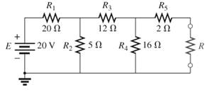
Fig.9.140
Expert Solution & Answer
Want to see the full answer?
Check out a sample textbook solution
Students have asked these similar questions
d) Terminal A is negative with respect to ter-
minals C and D.
TEST YOUR KNOWLEDGE
Refer to the voltage divider circuit shown
in Fig. 9-3. The source voltage is 100Vde and the
ammeter indicates a current of .02Ade. Resistor
R, is 3000 ohms and the voltage Ec.p between
1.
terminals C and D is (30Vdc.
Calculate the following:
3.
Refer to Fig. 9-1. If the value of resistor
Rs was changed to 6.5 kilohms, calculate the
following:
a) R, =
b) E4-5 "
Vdc
circuit current I
c) Eg.c =.
Vde
d) R; =
mAde
I=.02 A
Vdc
30y de
Oc
100vde
Vdc
Vdc
Fig. 9-3
4.
The sum of the voltage drops in a series
circuit is equal to
2.
State whether the following statements
regarding Fig. 9-3 are true or false.
a) Terminal B is negative with respect to ter-
5.
State the algebraic form of Kirchhoff's Law
minal A.
b) Terminal C is positive with respect to ter-
minal B.
c) A voltmeter connected between terminals
A and C would measure 40Vde,
9.10 Find the Thevenin equivalent circuit for the network external to the resistor R. Find the power delivered to
R when R=2k2 and R=100k2.
33 kn
120 mA
2.4 k
1.2 kn
*16. a. Determine the Thevénin equivalent circuit for the net-
work external to the resistor R in Fig. 9.140.
b. Find the current through the resistor R if its value is
20 Ω, 50 Ω, and 100 Ω
c. Without having the Thévenin equivalent circuit, what
would you have to do to find the current through the
resistor R for all the values of part (b)?
R1
R3
R5
20 Ω
12 N
20
E
20 V R2
R4
16 N
R
FIG. 9.140
Chapter 9 Solutions
Introductory Circuit Analysis (13th Edition)
Ch. 9 - (a) Using the superposition theorem, determine the...Ch. 9 - a. Using the superposition theorem, determine the...Ch. 9 - Using the superposition theorem, determine the...Ch. 9 - Using superposition, find the current l through...Ch. 9 - Using superposition, find the voltage VR3 for the...Ch. 9 - Using superposition, find the voltage V2 for the...Ch. 9 - Using superposition, find the current through R1...Ch. 9 - Using superposition, find the voltage across the...Ch. 9 - a. Find the Thévenin equivalent circuit for the...Ch. 9 - a. Find the Thévenin equivalent circuit for the...
Ch. 9 - a. Find the Thévenin equivalent circuit for the...Ch. 9 - Find the Thévenin equivalent circuit for the...Ch. 9 - Find the Thévenin equivalent circuit for the...Ch. 9 - Find the Thévenin equivalent circuit for the...Ch. 9 - a. Find the Thévenin equivalent circuit for the...Ch. 9 - Determine the Thevénin equivalent circuit for the...Ch. 9 - a. Determine the Thévenin equivalent circuit for...Ch. 9 - For the network in Fig. 9.142, find the Thévenin...Ch. 9 - For the transistor network in Fig. 9.143. a. Find...Ch. 9 - For each vertical set of measurements appearing in...Ch. 9 - For the network of Fig.9.145, find the Thévenin...Ch. 9 - a. Find the Norton equivalent circuit for the...Ch. 9 - a. Find the Norton equivalent circuit for the...Ch. 9 - Find the Norton equivalent circuit for the network...Ch. 9 - Find the Norton equivalent circuit for the network...Ch. 9 - Find the Norton equivalent circuit for the network...Ch. 9 - Find the Norton equivalent circuit for the network...Ch. 9 - Find the Norton equivalent circuit for the network...Ch. 9 - Find the Norton equivalent circuit for the network...Ch. 9 - a. Find the Norton equivalent circuit external to...Ch. 9 - a. Find the value of R for maximum power transfer...Ch. 9 - a. Find the value of R for maximum power transfer...Ch. 9 - a. Find the value of R for maximum power transfer...Ch. 9 - a. Find the value of RL in Fig.9.142 for maximum...Ch. 9 - a. For the network of Fig. 9.147, determine the...Ch. 9 - Find the resistance R1 in Fig.9.148 such that the...Ch. 9 - a. For the network in Fig.9.149, determine the...Ch. 9 - For the network in Fig. 9.150, determine the level...Ch. 9 - Using Millmans theorem, find the current through...Ch. 9 - Repeat Problem 38 for the network in Fig.9.152....Ch. 9 - Using Millmans theorem, find the current through...Ch. 9 - Using the dual of Millmans theorem, find the...Ch. 9 - Using the dual of Millmans theorem, find the...Ch. 9 - Using the substitution theorem, draw three...Ch. 9 - Using the substituion theorem, draw three...Ch. 9 - Using the substitution theorem, draw three...Ch. 9 - a. For the network in Fig. 9.159(a), determine the...Ch. 9 - a. For the network of Fig.9.16(a), determine the...Ch. 9 - a. Determine the voltageV for the network in...Ch. 9 - Using PSpice or Multisim and the superposition...Ch. 9 - Using PSpice or Multisim, determine the Thévenin...Ch. 9 - a. Using PSpice, plot the power delivered to the...Ch. 9 - Change the 300 resistor in Fig. 9.145 to a...
Additional Engineering Textbook Solutions
Find more solutions based on key concepts
Explain the main function of each of the following major components of a PLC: a. Processor module (CPU) b. I/O ...
Programmable Logic Controllers
What is the color code for a 365- five-band precision resistor with a tolerance of 5 percent?
ELECTRICITY FOR TRADES (LOOSELEAF)
With respect to the circuit in Fig. 5.90, (a) employ Thévenin’s theorem to determine the equivalent network see...
Loose Leaf for Engineering Circuit Analysis Format: Loose-leaf
Three point charges of equal magnitude q, that will yield a zero net electric field at the origin.
Engineering Electromagnetics
Electric power systems provide energy in a variety of commercial and industrial settings. Make a list of system...
Principles and Applications of Electrical Engineering
For the “tank” circuit in Fig. 14.79, find the resonant frequency.
Figure 14.79
For Probs. 14.39, 14.71, and 1...
Fundamentals of Electric Circuits
Knowledge Booster


Learn more about
Need a deep-dive on the concept behind this application? Look no further. Learn more about this topic, electrical-engineering and related others by exploring similar questions and additional content below.Similar questions
- Kirchoff's Laws - Example 9: O Use KCL to obtain currents i,, i, and i, in the circuit. 1 A 2 A 10 A i2 3 A iz DKS1113 Electric Circuits 19/43 08/01/12arrow_forward4. Find the total equivalent Resistance (Rab). 612 22 30 952 52arrow_forward9:23 P G ... ← Individu...n elect Samuel 1. Determine v1,v2, and the power dissipated in all the Resistors in the circuit shown below? 6 A 10 A 302 www Andualem wwwwwwww 2. Find the currents il through i4 and the voltage Vo in the circuit given below? % %252 10 2 892 12 V 492 12 www 3 V 552 www 192 1Ω 20 2 352 www 292 3. Using nodal analysis, find Vo in the circuit given below? 1₂ Firaol wwwwww {822 Ω 其 Print Headings Layout 30 Ω Σ Solomon 4% 4. Calculate Vo in the circuit shown below? 692 www 10 A 2 A Edit 60 ΩΣ 2% . | 46% | ... A)) Share Read Aloudarrow_forward
- An independent voltage source is characterized by a terminal voltage which Select one: a. is completely independent of the current through it. on b. is completely independent of the power dissipated by it. c. is completely dependent on the current through it. d. None of the abovearrow_forward1. Given the DC Series Circuit below: R₁ = 30 kr m E=IVE M R₂ = 15k^ Mu R₂ = 60kλ a) Draw the DC Series Equivalent Circuit and use it to find the total current, IT. b) What are the currents, I1, I2 and 13? c) Find the voltages V1, V2 and V3 by using Ohm's Law. d) Find the voltages V1, V2 and V3 by using Voltage Divider Rule. e) Calculate the Total Power, PT dissipated in this circuit. f) Compute the power dissipated by each resistor, P1, P2 and P3.arrow_forward9. (a) Find the Thevenin equivalent of the circuit shown to the left of terminals a and b. (b) Use the Thevenin equivalent circuit to find the power absorbed by a load resistor of 2 2. (c) Determine the value of R₁ that would absorb the maximum amount of power and find this power. 24 V 30 on 40arrow_forward
- • 1- a. For the network of Fig. 9.136, determine the value of R for maximum power to R. b. Determine the maximum power to R. c. Plot a curve of power to R versus R for R equal to . 1, 14. 14, 14, and 2 times the value obtained in 1(SA R4n E 24 V part (a). FIG. 9.136arrow_forward3. Using superposition, find the current through R for cach network of Fig. 9.125. R2 3.3 kN Ig D RE2.2 kN 4.7 k2 8 V 5 mA (a)arrow_forward22. a. Find the Norton equivalent circuit for the network externalto the resistor R in Fig. 9.133.b. Convert the Norton equivalent circuit to the Thévenin form.c. Find the Thévenin equivalent circuit using the Théveninapproach and compare results with part (b)arrow_forward
- https://docs.goog X p tabs together, right-click a tab z5bCAq361TACoM7x7Q/formResponse R= 3 Ohm Vs- 12 v O Got it Remind me later Q6: For the following circuit, find the total resistance between points A,B (Reg) and the total current from point B to A if the applied voltage VAB equal 30 v ww 152 22 102 G F 20 2 10 2 40 S2 30 2 ww Reg 6 Ohm It= 5 AO Reg =4.5 Ohm It= 6.66 A Reg 3 Ohm It= 10 A Reg -6 Ohm It= -5 AO none of the mentioned ABE wwwarrow_forward:Use Nodal analysis io determine the current in the 5 Ohm resistor and the voltage * across 9 A current supply 9A 4Ω B 50 www A www C 100 2 20 Ω ЗА www 4- www +arrow_forwardZVE O uo 9:.0 Asiacell Iiı. A docs.google.com blä 3 Find total resistance and Find .currents in the circuit in Fig R2 = 4 kN + R3 3 k2 R, 2 6 kN R4 15 kN V4 =E = 45 V Rt=8K, It=6mA Rt=8K, It=4.5mAarrow_forward
arrow_back_ios
SEE MORE QUESTIONS
arrow_forward_ios
Recommended textbooks for you
 Introductory Circuit Analysis (13th Edition)Electrical EngineeringISBN:9780133923605Author:Robert L. BoylestadPublisher:PEARSON
 Delmar's Standard Textbook Of ElectricityElectrical EngineeringISBN:9781337900348Author:Stephen L. HermanPublisher:Cengage Learning
 Programmable Logic ControllersElectrical EngineeringISBN:9780073373843Author:Frank D. PetruzellaPublisher:McGraw-Hill Education
 Fundamentals of Electric CircuitsElectrical EngineeringISBN:9780078028229Author:Charles K Alexander, Matthew SadikuPublisher:McGraw-Hill Education
 Electric Circuits. (11th Edition)Electrical EngineeringISBN:9780134746968Author:James W. Nilsson, Susan RiedelPublisher:PEARSON
 Engineering ElectromagneticsElectrical EngineeringISBN:9780078028151Author:Hayt, William H. (william Hart), Jr, BUCK, John A.Publisher:Mcgraw-hill Education,
Introductory Circuit Analysis (13th Edition)
Electrical Engineering
ISBN:9780133923605
Author:Robert L. Boylestad
Publisher:PEARSON
Delmar's Standard Textbook Of Electricity
Electrical Engineering
ISBN:9781337900348
Author:Stephen L. Herman
Publisher:Cengage Learning
Programmable Logic Controllers
Electrical Engineering
ISBN:9780073373843
Author:Frank D. Petruzella
Publisher:McGraw-Hill Education
Fundamentals of Electric Circuits
Electrical Engineering
ISBN:9780078028229
Author:Charles K Alexander, Matthew Sadiku
Publisher:McGraw-Hill Education
Electric Circuits. (11th Edition)
Electrical Engineering
ISBN:9780134746968
Author:James W. Nilsson, Susan Riedel
Publisher:PEARSON
Engineering Electromagnetics
Electrical Engineering
ISBN:9780078028151
Author:Hayt, William H. (william Hart), Jr, BUCK, John A.
Publisher:Mcgraw-hill Education,
Thevenin's Theorem; Author: Neso Academy;https://www.youtube.com/watch?v=veAFVTIpKyM;License: Standard YouTube License, CC-BY