
Introductory Circuit Analysis (13th Edition)
13th Edition
ISBN: 9780133923605
Author: Robert L. Boylestad
Publisher: PEARSON
expand_more
expand_more
format_list_bulleted
Videos
Textbook Question
Chapter 9, Problem 10P
a. Find the Thévenin equivalent circuit for the network external to the resistor R for the network in Fig.9.134.
b. Find the power delivered to R when R is 2k
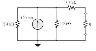
Fig.9.134
Expert Solution & Answer
Want to see the full answer?
Check out a sample textbook solution
Students have asked these similar questions
Find current I0 n the network of Fig. 9.52.
Determine the equivalent resistance between terminals a and b.
9.6540 Q
8.2756Q
9.2715Q
O 8.3025 Q
R5
5 Ohms
.R1
www
1 Ohm
R2
2 Ohms
R6
6 Ohms
R3
3 Ohms
www
R4
4 Ohms
*16. a. Determine the Thevénin equivalent circuit for the net-
work external to the resistor R in Fig. 9.140.
b. Find the current through the resistor R if its value is
20 Ω, 50 Ω, and 100 Ω
c. Without having the Thévenin equivalent circuit, what
would you have to do to find the current through the
resistor R for all the values of part (b)?
R1
R3
R5
20 Ω
12 N
20
E
20 V R2
R4
16 N
R
FIG. 9.140
Chapter 9 Solutions
Introductory Circuit Analysis (13th Edition)
Ch. 9 - (a) Using the superposition theorem, determine the...Ch. 9 - a. Using the superposition theorem, determine the...Ch. 9 - Using the superposition theorem, determine the...Ch. 9 - Using superposition, find the current l through...Ch. 9 - Using superposition, find the voltage VR3 for the...Ch. 9 - Using superposition, find the voltage V2 for the...Ch. 9 - Using superposition, find the current through R1...Ch. 9 - Using superposition, find the voltage across the...Ch. 9 - a. Find the Thévenin equivalent circuit for the...Ch. 9 - a. Find the Thévenin equivalent circuit for the...
Ch. 9 - a. Find the Thévenin equivalent circuit for the...Ch. 9 - Find the Thévenin equivalent circuit for the...Ch. 9 - Find the Thévenin equivalent circuit for the...Ch. 9 - Find the Thévenin equivalent circuit for the...Ch. 9 - a. Find the Thévenin equivalent circuit for the...Ch. 9 - Determine the Thevénin equivalent circuit for the...Ch. 9 - a. Determine the Thévenin equivalent circuit for...Ch. 9 - For the network in Fig. 9.142, find the Thévenin...Ch. 9 - For the transistor network in Fig. 9.143. a. Find...Ch. 9 - For each vertical set of measurements appearing in...Ch. 9 - For the network of Fig.9.145, find the Thévenin...Ch. 9 - a. Find the Norton equivalent circuit for the...Ch. 9 - a. Find the Norton equivalent circuit for the...Ch. 9 - Find the Norton equivalent circuit for the network...Ch. 9 - Find the Norton equivalent circuit for the network...Ch. 9 - Find the Norton equivalent circuit for the network...Ch. 9 - Find the Norton equivalent circuit for the network...Ch. 9 - Find the Norton equivalent circuit for the network...Ch. 9 - Find the Norton equivalent circuit for the network...Ch. 9 - a. Find the Norton equivalent circuit external to...Ch. 9 - a. Find the value of R for maximum power transfer...Ch. 9 - a. Find the value of R for maximum power transfer...Ch. 9 - a. Find the value of R for maximum power transfer...Ch. 9 - a. Find the value of RL in Fig.9.142 for maximum...Ch. 9 - a. For the network of Fig. 9.147, determine the...Ch. 9 - Find the resistance R1 in Fig.9.148 such that the...Ch. 9 - a. For the network in Fig.9.149, determine the...Ch. 9 - For the network in Fig. 9.150, determine the level...Ch. 9 - Using Millmans theorem, find the current through...Ch. 9 - Repeat Problem 38 for the network in Fig.9.152....Ch. 9 - Using Millmans theorem, find the current through...Ch. 9 - Using the dual of Millmans theorem, find the...Ch. 9 - Using the dual of Millmans theorem, find the...Ch. 9 - Using the substitution theorem, draw three...Ch. 9 - Using the substituion theorem, draw three...Ch. 9 - Using the substitution theorem, draw three...Ch. 9 - a. For the network in Fig. 9.159(a), determine the...Ch. 9 - a. For the network of Fig.9.16(a), determine the...Ch. 9 - a. Determine the voltageV for the network in...Ch. 9 - Using PSpice or Multisim and the superposition...Ch. 9 - Using PSpice or Multisim, determine the Thévenin...Ch. 9 - a. Using PSpice, plot the power delivered to the...Ch. 9 - Change the 300 resistor in Fig. 9.145 to a...
Additional Engineering Textbook Solutions
Find more solutions based on key concepts
When travelers from the USA and Canada visit Europe, they encounter a different power distribution system. Wall...
Electric machinery fundamentals
How many coulombs do 93.8 1016 electrons represent?
Principles Of Electric Circuits
Electric power systems provide energy in a variety of commercial and industrial settings. Make a list of system...
Principles and Applications of Electrical Engineering
Identify the type of input and output configuration for each diff-amp in Figure 18-35.
Electronics Fundamentals: Circuits, Devices & Applications
Does the severity of an electric shock increase ordecrease with eh of the following changes? a. A decrease in t...
Electric Motors and Control Systems
Design an ideal inverting op-amp circuit such that the voltage gain is Av=25 . The maximum current in any resis...
Microelectronics: Circuit Analysis and Design
Knowledge Booster


Learn more about
Need a deep-dive on the concept behind this application? Look no further. Learn more about this topic, electrical-engineering and related others by exploring similar questions and additional content below.Similar questions
- m Find v, and i, in the circuit of Fig. 9 A 22 82arrow_forwardCalculate the value of Zab in the network of Fig. 9.79. -19 2 a o j6 2 792 -192 20 2 20 2 102 bo elearrow_forwardSolve V, and V2. Also solve for the value of the current flowing through the j5 ohm inductor. Use Nodal Analysis. If the circuit diagram below is not loading, please refer to this attached file: Nodal Analysis Circuit Diagram-1.pdf 100,/60 V V2 42 V j5 0 -j9 N 20arrow_forward
- Three parallel branches each containing one pure element have an applied voltage v = 200 sin 1000t volts. The branches contain R = 300 ohms, L = 0.5 H and C = 10 uF respectively. Find the total current, the angle between IT and the applied voltage and magnitude of impedance.arrow_forwardFind this results using Multisim/Pspice Software, PLEASE HELP ASAParrow_forward1. Given the DC Series Circuit below: R₁ = 30 kr m E=IVE M R₂ = 15k^ Mu R₂ = 60kλ a) Draw the DC Series Equivalent Circuit and use it to find the total current, IT. b) What are the currents, I1, I2 and 13? c) Find the voltages V1, V2 and V3 by using Ohm's Law. d) Find the voltages V1, V2 and V3 by using Voltage Divider Rule. e) Calculate the Total Power, PT dissipated in this circuit. f) Compute the power dissipated by each resistor, P1, P2 and P3.arrow_forward
- 3. Using superposition, find the current I through the 24 V source in Fig. 9.121. E₁ = + 42 V R₁ 18 Ω R₂ 90 R₁ 10 Q2 24 V +/²1 + E₂ 1 R3 15 Ω FIG. 9.121 Problem 3.arrow_forwardObtain the voltage Vin the network of Fig. 9- 28, using the mesh current method. -j2 N 5/30° V 10/0° V j5 N I2 10 N 5 Ω 2Ω -j2 N I3 10 N + V, Fig. 9-28arrow_forwardPlease show your detailed solution Number 19 How much power is represented by a circuit in which the voltage and current equations are e = 180 sin314t and i = 42 sin 314t? A. 771 W C. 7560 W B. 3780 W D. 5346 Warrow_forward
- An independent voltage source is characterized by a terminal voltage which Select one: a. is completely independent of the current through it. on b. is completely independent of the power dissipated by it. c. is completely dependent on the current through it. d. None of the abovearrow_forwardA. Find z11. Express your answer in ohms in terms of S. B. Find z12. Express your answer in ohms in terms of S. C. Find z21. Express your answer in ohms in terms of S. D. Find z22. Express your answer in ohms in terms of S.arrow_forwardxE Assig x < hw9 x M Solve x calcul x Assig x W 9.10 S X multi X New Tab om/u/0/c/MjM3MzQxOTI2NjA1/a/MJQ3OTEWOTY4MZY3/details sdep, Page 1 of 2 6. Find the Thevenin and Norton equivalent of the following circuit across terminals a and b. f) 100 mA UN S'L Answers: 1. VTH = 69.27 V RTH = 7.3178 2. VTH = -150 V U 00s = H1 RN = 10.64 4. IN = -12.5 mA 11:30 F 31-01-20 arch ON3 p ツv ② f12 insert Oly I14 61 144 f5arrow_forward
arrow_back_ios
SEE MORE QUESTIONS
arrow_forward_ios
Recommended textbooks for you
 Introductory Circuit Analysis (13th Edition)Electrical EngineeringISBN:9780133923605Author:Robert L. BoylestadPublisher:PEARSON
 Delmar's Standard Textbook Of ElectricityElectrical EngineeringISBN:9781337900348Author:Stephen L. HermanPublisher:Cengage Learning
 Programmable Logic ControllersElectrical EngineeringISBN:9780073373843Author:Frank D. PetruzellaPublisher:McGraw-Hill Education
 Fundamentals of Electric CircuitsElectrical EngineeringISBN:9780078028229Author:Charles K Alexander, Matthew SadikuPublisher:McGraw-Hill Education
 Electric Circuits. (11th Edition)Electrical EngineeringISBN:9780134746968Author:James W. Nilsson, Susan RiedelPublisher:PEARSON
 Engineering ElectromagneticsElectrical EngineeringISBN:9780078028151Author:Hayt, William H. (william Hart), Jr, BUCK, John A.Publisher:Mcgraw-hill Education,
Introductory Circuit Analysis (13th Edition)
Electrical Engineering
ISBN:9780133923605
Author:Robert L. Boylestad
Publisher:PEARSON
Delmar's Standard Textbook Of Electricity
Electrical Engineering
ISBN:9781337900348
Author:Stephen L. Herman
Publisher:Cengage Learning
Programmable Logic Controllers
Electrical Engineering
ISBN:9780073373843
Author:Frank D. Petruzella
Publisher:McGraw-Hill Education
Fundamentals of Electric Circuits
Electrical Engineering
ISBN:9780078028229
Author:Charles K Alexander, Matthew Sadiku
Publisher:McGraw-Hill Education
Electric Circuits. (11th Edition)
Electrical Engineering
ISBN:9780134746968
Author:James W. Nilsson, Susan Riedel
Publisher:PEARSON
Engineering Electromagnetics
Electrical Engineering
ISBN:9780078028151
Author:Hayt, William H. (william Hart), Jr, BUCK, John A.
Publisher:Mcgraw-hill Education,
Lesson 2 - Source Transformations, Part 2 (Engineering Circuits); Author: Math and Science;https://www.youtube.com/watch?v=7gno74RhVGQ;License: Standard Youtube License