
Loose Leaf for Engineering Circuit Analysis Format: Loose-leaf
9th Edition
ISBN: 9781259989452
Author: Hayt
Publisher: Mcgraw Hill Publishers
expand_more
expand_more
format_list_bulleted
Concept explainers
Videos
Textbook Question
Chapter 6, Problem 54E
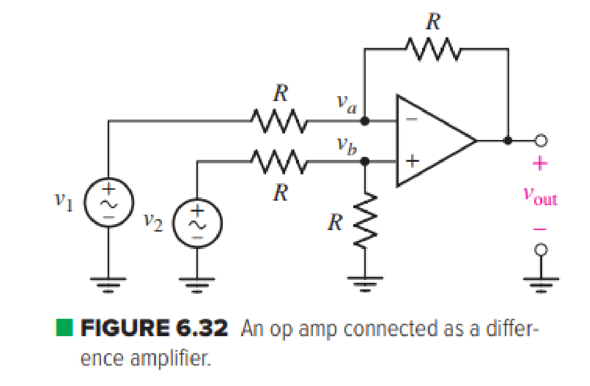
The difference amplifier circuit in Fig. 6.32 has a common-mode signal that can vary by up to 5 V. How would this variation in common-mode input change the output voltage for cases of using a μA741, LM324, and LT1001 op amp?
Expert Solution & Answer
Want to see the full answer?
Check out a sample textbook solution
Students have asked these similar questions
Design a voltage to current converter amplifier. Assume that you have 5v input voltage to the non-inverting input with a frequency of 60hz and another input voltage to the inverting input with a frequency of 60hz, place it before the input resistance. What should be the value of your voltage input in inverting input and input resistance to get a reading of 38.22mA at exactly 22.20ms and what is the shape waveform of the current?
What is the value of Vin?Vin = ____ volts
Design a voltage to current converter amplifier. Assume that you have 5v input voltage to the non-inverting input with a frequency of 60hz
and another input voltage to the inverting input with a frequency of 60hz, place it before the input resistance. What should be the value of
your voltage input in inverting input and input resistance to get a reading of 38.22mA at exactly 22.20ms and what is the shape waveform
of the current?
Cursor 1
I(R2)
Horz: 22.204037ms
Vert: 38.277447mA
What is the value of Vin?
No need to include the Units.
Vin =
volts
Design a voltage to current converter amplifier. Assume that you have 5v input voltage to the non-inverting input with a frequency of 60hz and another input voltage to the inverting input with a frequency of 60hz, place it before the input resistance. What should be the value of your voltage input in inverting input and input resistance to get a reading of 38.22mA at exactly 22.20ms and what is the shape waveform of the current?
What is the value of Rin in ohms?Rin = ____ ohms
Chapter 6 Solutions
Loose Leaf for Engineering Circuit Analysis Format: Loose-leaf
Ch. 6.2 - Derive an expression for vout in terms of vin for...Ch. 6.2 - Prob. 2PCh. 6.3 - An historic bridge is showing signs of...Ch. 6.4 - Design a circuit that provides a 12 V output if a...Ch. 6.4 - Design a noninverting Schmitt trigger that that...Ch. 6.5 - Assuming a finite open-loop gain (A), a finite...Ch. 6.5 - Use SPICE to simulate a voltage follower using an...Ch. 6 - For the op amp circuit shown in Fig. 6.39,...Ch. 6 - FIGURE 6.39 Determine the power dissipated by a...Ch. 6 - For the circuit of Fig. 6.40, calculate vout if...
Ch. 6 - For the circuit in Fig. 6.40, find the values of...Ch. 6 - (a) Design a circuit which converts a voltage...Ch. 6 - Prob. 6ECh. 6 - For the circuit of Fig. 6.40, R1 = RL = 50 ....Ch. 6 - Prob. 8ECh. 6 - (a) Design a circuit using only a single op amp...Ch. 6 - Prob. 11ECh. 6 - Determine the output voltage v0 and the current...Ch. 6 - Prob. 13ECh. 6 - Prob. 14ECh. 6 - Prob. 15ECh. 6 - Prob. 16ECh. 6 - Consider the amplifier circuit shown in Fig. 6.46....Ch. 6 - Prob. 18ECh. 6 - Prob. 19ECh. 6 - Prob. 20ECh. 6 - Referring to Fig. 6.49, sketch vout as a function...Ch. 6 - Repeat Exercise 21 using a parameter sweep in...Ch. 6 - Obtain an expression for vout as labeled in the...Ch. 6 - Prob. 24ECh. 6 - Prob. 25ECh. 6 - Prob. 26ECh. 6 - Prob. 27ECh. 6 - Prob. 28ECh. 6 - Prob. 29ECh. 6 - Prob. 30ECh. 6 - Prob. 31ECh. 6 - Determine the value of Vout for the circuit in...Ch. 6 - Calculate V0 for the circuit in Fig. 6.55. FIGURE...Ch. 6 - Prob. 34ECh. 6 - The temperature alarm circuit in Fig. 6.56...Ch. 6 - Prob. 36ECh. 6 - For the circuit depicted in Fig. 6.57, sketch the...Ch. 6 - For the circuit depicted in Fig. 6.58, (a) sketch...Ch. 6 - For the circuit depicted in Fig. 6.59, sketch the...Ch. 6 - In digital logic applications, a +5 V signal...Ch. 6 - Using the temperature sensor in the circuit in...Ch. 6 - Examine the comparator Schmitt trigger circuit in...Ch. 6 - Design the circuit values for the single supply...Ch. 6 - For the instrumentation amplifier shown in Fig....Ch. 6 - A common application for instrumentation...Ch. 6 - (a) Employ the parameters listed in Table 6.3 for...Ch. 6 - Prob. 49ECh. 6 - For the circuit of Fig. 6.62, calculate the...Ch. 6 - Prob. 51ECh. 6 - FIGURE 6.63 (a) For the circuit of Fig. 6.63, if...Ch. 6 - The difference amplifier circuit in Fig. 6.32 has...Ch. 6 - Prob. 55ECh. 6 - Prob. 56ECh. 6 - Prob. 57ECh. 6 - Prob. 58ECh. 6 - Prob. 59ECh. 6 - Prob. 60ECh. 6 - A fountain outside a certain office building is...Ch. 6 - For the circuit of Fig. 6.44, let all resistor...
Knowledge Booster


Learn more about
Need a deep-dive on the concept behind this application? Look no further. Learn more about this topic, electrical-engineering and related others by exploring similar questions and additional content below.Similar questions
- Figure 6 (a) shows the circuit diagram for a differential amphfier. You may assume that M and M, have identical parameters. Referring to Figure 6 (a): (a) What kind of amplifier is it? What is its role in a three-stage op amp? Draw the small signal equivalent eircuit and derive the differential voltage gain Aag. For the analysis consider RDI RD2 >>Rp State any assumption. (b) RD. gml gm gm, and r re=r What is the new Adr in the circuit of Figure 6 (b), where a PMOS current source has replaced the two drain resistors Ror R Rp and a NMOS current sink has replaced the source resistor Rs? (c) What are the advantages in using the circuit of Figure 6 (b) instead of Figure 6 (a) to realize an op amp? (d) Ven Ms Mg Rp1 Rpa Vo HM, My M Ma M3 Vss 0 V Vss 0 V Figure 6(b) Figure 6 (a)arrow_forwardAlso sketch the large signal DC equivalent circuit Replace with small signal T model only beta =100 If any of teh resistor value not mentioned, take 1k ohm or 10k ohm as per choicePlease solve all showing all the detailsarrow_forwardWhat are circuits can used to design Class B amplifier ? explain the important features ? for eacharrow_forward
- 6b. The transistor consists of three terminals. The main reason for designing configurations is that it requires four terminals in order to provide the input and the output connections of the circuit for effective amplification. Now in your own words describe how Bipolar Transistors Transistor ( BJT ) various configurations are designed with relating diagrams. In your own estimation evalute which one is most widely used when looking at appreciable output for an amplifier?arrow_forwardOperational amplifiers can be used to build circuits that perform mathematical operations. List the different standard operational amplifier circuits and explain the use of any four of these circuits with examples.arrow_forwardThe circuit shown in Fig. 4 provides transfer characteristics with +7.5 V levels at the output vo. When v 0 V, a current of 0.5 mA flows in the feedback resistor (R2) and a current of 1.0 mA flows through the zener-diodes. Assume that the output saturation levels of the op-amp are ±12.0 V, the forward-drop voltage of the zener-diode is 0.7 V, and the value of R, is equal to R2. a) Specify the zener-voltages of the zener diodes. b) Find the values of all resistors. R2 R1 R Z Z, Fig. 4arrow_forward
- A circuit is to be biased at a current of 5 mA and achieve an input resistance of at least 1MΩ. Should a BJT or FET be chosen for this circuit and why?arrow_forwardFor an op-amp having a slew rate of SR=3.6 V/us. What is the maximum voltage gain that is used when the input signal varies by 4.4 v in 9 us?arrow_forwardA circuit is built around a bi-polar NPN transisor. The base network has a diode and a capacitor in series while the collector is connected to the power supply through a resistor. if the resistor is connected to ground; i) draw the circuit ii) provide all the masking layout of the circuitarrow_forward
- Q.2 Design op-amp circuit to produce the output Vo 6V, using both inverting and non- inverting circuits.arrow_forward1. Design a circuit to convert from voltage to current using an operational amplifier. The practical values of voltage should varies from 1V to 5V to obtain the output current such that minimum current should be 4mA and maximum current to be 20 mA. 2. Clearly outline the detailed design procedure including all the assumptions made in the report including cost analysis.arrow_forwardDraw the equivalent circuit for summing amplifier and voltage amplifier inverting non-invertingarrow_forward
arrow_back_ios
SEE MORE QUESTIONS
arrow_forward_ios
Recommended textbooks for you
 Introductory Circuit Analysis (13th Edition)Electrical EngineeringISBN:9780133923605Author:Robert L. BoylestadPublisher:PEARSON
 Delmar's Standard Textbook Of ElectricityElectrical EngineeringISBN:9781337900348Author:Stephen L. HermanPublisher:Cengage Learning
 Programmable Logic ControllersElectrical EngineeringISBN:9780073373843Author:Frank D. PetruzellaPublisher:McGraw-Hill Education
 Fundamentals of Electric CircuitsElectrical EngineeringISBN:9780078028229Author:Charles K Alexander, Matthew SadikuPublisher:McGraw-Hill Education
 Electric Circuits. (11th Edition)Electrical EngineeringISBN:9780134746968Author:James W. Nilsson, Susan RiedelPublisher:PEARSON
 Engineering ElectromagneticsElectrical EngineeringISBN:9780078028151Author:Hayt, William H. (william Hart), Jr, BUCK, John A.Publisher:Mcgraw-hill Education,
Introductory Circuit Analysis (13th Edition)
Electrical Engineering
ISBN:9780133923605
Author:Robert L. Boylestad
Publisher:PEARSON
Delmar's Standard Textbook Of Electricity
Electrical Engineering
ISBN:9781337900348
Author:Stephen L. Herman
Publisher:Cengage Learning
Programmable Logic Controllers
Electrical Engineering
ISBN:9780073373843
Author:Frank D. Petruzella
Publisher:McGraw-Hill Education
Fundamentals of Electric Circuits
Electrical Engineering
ISBN:9780078028229
Author:Charles K Alexander, Matthew Sadiku
Publisher:McGraw-Hill Education
Electric Circuits. (11th Edition)
Electrical Engineering
ISBN:9780134746968
Author:James W. Nilsson, Susan Riedel
Publisher:PEARSON
Engineering Electromagnetics
Electrical Engineering
ISBN:9780078028151
Author:Hayt, William H. (william Hart), Jr, BUCK, John A.
Publisher:Mcgraw-hill Education,
Current Divider Rule; Author: Neso Academy;https://www.youtube.com/watch?v=hRU1mKWUehY;License: Standard YouTube License, CC-BY