
Loose Leaf for Engineering Circuit Analysis Format: Loose-leaf
9th Edition
ISBN: 9781259989452
Author: Hayt
Publisher: Mcgraw Hill Publishers
expand_more
expand_more
format_list_bulleted
Concept explainers
Videos
Textbook Question
Chapter 6, Problem 2E
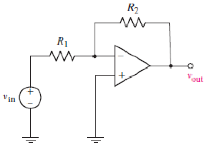
FIGURE 6.39
Determine the power dissipated by a 100 Ω resistor connected between ground and the output pin of the op amp of Fig. 6.39 if vin = 4 V and (a) R1 = 2R2; (b) R1 = 1 kΩ and R2 = 22 kΩ; (c) R1 = 100 Ω and R2 = 101 Ω.
Expert Solution & Answer
Want to see the full answer?
Check out a sample textbook solution
Students have asked these similar questions
Exercise
The buck dc-dc converter of Fig. 6-3a has the following parameters:
V = 50 V
D = 0.4
L = 400 µH
C = 100 µ.F
f= 20 kHz
R= 20 N
Assuming ideal components, calculate (a) the output voltage V, (b) the maximum and
minimum inductor current, and (c) the output voltage ripple.
For the inverting amplifier in Fig. 6_3, if Vin=-50 cos10t (V), R₁= 200 Ohm and R-20 Ohm; what is Vout
?
Vin
5 cos10t (V)
- 5 cos10t (V)
R1
ww
Fig. 6_3
-1000 cos10t (V)
O 1000 cos10t (V)
Rf
ww
Vout
For the circuit below, let Vin = 8 V. You are to select resistor values to guarantee an output voltage with magnitude 4V. Assume that the op amps are ideal.
R₁
FIGURE 6.51
R₂
www
R3
50 ΚΩ
200 ΚΩ
www
out
Chapter 6 Solutions
Loose Leaf for Engineering Circuit Analysis Format: Loose-leaf
Ch. 6.2 - Derive an expression for vout in terms of vin for...Ch. 6.2 - Prob. 2PCh. 6.3 - An historic bridge is showing signs of...Ch. 6.4 - Design a circuit that provides a 12 V output if a...Ch. 6.4 - Design a noninverting Schmitt trigger that that...Ch. 6.5 - Assuming a finite open-loop gain (A), a finite...Ch. 6.5 - Use SPICE to simulate a voltage follower using an...Ch. 6 - For the op amp circuit shown in Fig. 6.39,...Ch. 6 - FIGURE 6.39 Determine the power dissipated by a...Ch. 6 - For the circuit of Fig. 6.40, calculate vout if...
Ch. 6 - For the circuit in Fig. 6.40, find the values of...Ch. 6 - (a) Design a circuit which converts a voltage...Ch. 6 - Prob. 6ECh. 6 - For the circuit of Fig. 6.40, R1 = RL = 50 ....Ch. 6 - Prob. 8ECh. 6 - (a) Design a circuit using only a single op amp...Ch. 6 - Prob. 11ECh. 6 - Determine the output voltage v0 and the current...Ch. 6 - Prob. 13ECh. 6 - Prob. 14ECh. 6 - Prob. 15ECh. 6 - Prob. 16ECh. 6 - Consider the amplifier circuit shown in Fig. 6.46....Ch. 6 - Prob. 18ECh. 6 - Prob. 19ECh. 6 - Prob. 20ECh. 6 - Referring to Fig. 6.49, sketch vout as a function...Ch. 6 - Repeat Exercise 21 using a parameter sweep in...Ch. 6 - Obtain an expression for vout as labeled in the...Ch. 6 - Prob. 24ECh. 6 - Prob. 25ECh. 6 - Prob. 26ECh. 6 - Prob. 27ECh. 6 - Prob. 28ECh. 6 - Prob. 29ECh. 6 - Prob. 30ECh. 6 - Prob. 31ECh. 6 - Determine the value of Vout for the circuit in...Ch. 6 - Calculate V0 for the circuit in Fig. 6.55. FIGURE...Ch. 6 - Prob. 34ECh. 6 - The temperature alarm circuit in Fig. 6.56...Ch. 6 - Prob. 36ECh. 6 - For the circuit depicted in Fig. 6.57, sketch the...Ch. 6 - For the circuit depicted in Fig. 6.58, (a) sketch...Ch. 6 - For the circuit depicted in Fig. 6.59, sketch the...Ch. 6 - In digital logic applications, a +5 V signal...Ch. 6 - Using the temperature sensor in the circuit in...Ch. 6 - Examine the comparator Schmitt trigger circuit in...Ch. 6 - Design the circuit values for the single supply...Ch. 6 - For the instrumentation amplifier shown in Fig....Ch. 6 - A common application for instrumentation...Ch. 6 - (a) Employ the parameters listed in Table 6.3 for...Ch. 6 - Prob. 49ECh. 6 - For the circuit of Fig. 6.62, calculate the...Ch. 6 - Prob. 51ECh. 6 - FIGURE 6.63 (a) For the circuit of Fig. 6.63, if...Ch. 6 - The difference amplifier circuit in Fig. 6.32 has...Ch. 6 - Prob. 55ECh. 6 - Prob. 56ECh. 6 - Prob. 57ECh. 6 - Prob. 58ECh. 6 - Prob. 59ECh. 6 - Prob. 60ECh. 6 - A fountain outside a certain office building is...Ch. 6 - For the circuit of Fig. 6.44, let all resistor...
Knowledge Booster


Learn more about
Need a deep-dive on the concept behind this application? Look no further. Learn more about this topic, electrical-engineering and related others by exploring similar questions and additional content below.Similar questions
- The Junction Gate Field Effect Transistor is one of the simplest types of fieldeffect transistor. It is a three-terminal semiconductor device .One of its function is, it serve as an amplifier. As an Engineer you are to design a single stage JFET Amplifier. Explain in your own words this circuit operates, identifyingarrow_forwardI μA For the op-amp circuit of Fig. 6.21, find Vo 10 ΚΩ wwwwww * V₁ V₂ wwwwww 99 ΚΩ wwww 1 ΚΩ = RL wwwww T Voarrow_forwardAn op amp has Vsat = +/- 13 V, SR = 1.7 V/μs, and is used as a comparator. What is the approximate time it takes to transition from one output state to the other?arrow_forward
- For the difference amplifier in Fig. 6_4, if V₁ = 3 sin10t (V), V₂ = 6 sin 10t (V), and R= 20 Ohm, what is Vout? V₁ V₂ 3 sin10t (V) -3 sin10t (V) -9 sin10t (V) 9 sin 10t (V) R R www R Fig. 6_4 R ww - Vout RLarrow_forwardThe measuring range of a MC instrument is found to be (0 – 800) mA. This low range instrument is connected with a multiplier resistance of 120 Ω, in order to measure potential difference up to 120V. Determine the resistance of the instrumentarrow_forwardThe Junction Gate Field Effect Transistor is one of the simplest types of field-effect transistor. It is a three-terminal semiconductor device .One of its function is, it serve as an amplifier. As an Engineer you are to design a single stage JFET Amplifier. Explain in your own words this circuit operates, identifying each component in your design circuit and state their functionsarrow_forward
- Design an op-amp circuit that can perform this operation: Vo 2V2 Draw the circuit diagram and show all the calculations as well as your assumptions. Maximum file size: 100MB, maximarrow_forward2. Referring to Fig. 6, develop a formula that will give the voltage gain, VV₁ in terms of F and the feedback resistance, R₁. Assume the voltage difference between pins 2 and 3 to be zero, and the current flowing into these pins also to be zero. V₁ 2 3 + 741 +15v 7 4 -15v 6 R₁=25k Vo R₁ Figure 6. Non-Inverting Amplifierarrow_forwardA silicon photodiode is connected to an op-amp as indicated. Under an illuminance of 500 lux, the photocurrent Ip is 80 nA. R = 1ΜΩ V out a) Write down the values of I₁, I2 and lp. From these values, deduce the output voltage. b) Briefly describe how this circuit works. c) Will this circuit work under sunlight? The illuminance of sunlight is about 100,000 lux. You may assume the photocurrent respond linearly with incident light flux, and the op-amp is powered between 9V alkaline cell. (i.e., V* = 9V, V¯ at ground).arrow_forward
- Level measurement in a sump tank is provided by a transducer scaled as 1.998 V/m. A pump is to be turned on by application of 7 V when the sump level exceeds 6.5 m. The pump is to be turned back off when the sump level drops to 3.8 m. Find VH and VL .Given R1/R2 = 1.5. a) VH= b) VL=arrow_forward1. For the op amp circuit shown in Fig. 6.39, calculate vout if (a) R₁ = R₂ = 100 $2 and vin = 5 V; (b) R₂ = 200 R₁ and vin = 1 V; (c) R₁ = 4.7 ks, R₂ = 47 k2, and Vin = 20 sin 5t V. Vin R₁ www R₂ ww + Voutarrow_forwardFor the signal and circuit of Figure 6, the op-amp has a slew rate of SR=0.75 V/µs. a) Calculate the maximum frequency that may be used. b) Determine if the signal will be an amplified duplicate at the output.arrow_forward
arrow_back_ios
SEE MORE QUESTIONS
arrow_forward_ios
Recommended textbooks for you
 Introductory Circuit Analysis (13th Edition)Electrical EngineeringISBN:9780133923605Author:Robert L. BoylestadPublisher:PEARSON
 Delmar's Standard Textbook Of ElectricityElectrical EngineeringISBN:9781337900348Author:Stephen L. HermanPublisher:Cengage Learning
 Programmable Logic ControllersElectrical EngineeringISBN:9780073373843Author:Frank D. PetruzellaPublisher:McGraw-Hill Education
 Fundamentals of Electric CircuitsElectrical EngineeringISBN:9780078028229Author:Charles K Alexander, Matthew SadikuPublisher:McGraw-Hill Education
 Electric Circuits. (11th Edition)Electrical EngineeringISBN:9780134746968Author:James W. Nilsson, Susan RiedelPublisher:PEARSON
 Engineering ElectromagneticsElectrical EngineeringISBN:9780078028151Author:Hayt, William H. (william Hart), Jr, BUCK, John A.Publisher:Mcgraw-hill Education,
Introductory Circuit Analysis (13th Edition)
Electrical Engineering
ISBN:9780133923605
Author:Robert L. Boylestad
Publisher:PEARSON
Delmar's Standard Textbook Of Electricity
Electrical Engineering
ISBN:9781337900348
Author:Stephen L. Herman
Publisher:Cengage Learning
Programmable Logic Controllers
Electrical Engineering
ISBN:9780073373843
Author:Frank D. Petruzella
Publisher:McGraw-Hill Education
Fundamentals of Electric Circuits
Electrical Engineering
ISBN:9780078028229
Author:Charles K Alexander, Matthew Sadiku
Publisher:McGraw-Hill Education
Electric Circuits. (11th Edition)
Electrical Engineering
ISBN:9780134746968
Author:James W. Nilsson, Susan Riedel
Publisher:PEARSON
Engineering Electromagnetics
Electrical Engineering
ISBN:9780078028151
Author:Hayt, William H. (william Hart), Jr, BUCK, John A.
Publisher:Mcgraw-hill Education,
Current Divider Rule; Author: Neso Academy;https://www.youtube.com/watch?v=hRU1mKWUehY;License: Standard YouTube License, CC-BY