
Videos
Two steel lubes are shrink-filled together where the nominal diameters are 40, 45, and 50 mm. Careful measurement before fitting determined the diametral interference between the tubes to be 0.062 mm. After the fit. the assembly is subjected to a torque of 900 N · m and a bending-moment of 675 N · m. Assuming no slipping between the cylinders, analyze the outer cylinder at the inner and outer radius. Determine the factor of safety using distortion energy with Sv = 415 MPa.
The factor of safety using distortion energy theory.
Answer to Problem 74P
The factor of safety using distortion energy theory for inner radius is
The factor of safety using distortion energy theory for outer radius is
Explanation of Solution
Write the expression for contact pressure.
Here, the contact pressure is
Write the expression for inner radius.
Here, the inner radius is
Write the expression for outer radius.
Here, the outer radius is
Write the expression for tangential stress at outer radius for outer member.
Here, the tangential stress at outer radius for outer member is
Write the expression for tangential stress for inner member.
Here, the tangential stress for inner member is
Write the expression for radial stress for inner member.
Here, the radial stress for inner member is
Write the expression for second moment of area.
Here, the second moment of area is
Write the expression for stress.
Here, the stress in
Write the expression for second polar moment of area.
Here, the second polar moment of area is
Write the expression for shear stress.
Here, the shear stress is
Write the expression for von Mises stress for outer radius.
Here, the von Mises stress is
Calculate factor of safety for outer radius.
Here, the factor of safety for outer radius is
Write the expression for von Mises stress for inner radius.
Here, the von Mises stress for inner radius is
Calculate the factor of safety for inner radius.
Here, the factor of safety for inner radius is
Write the expression for nominal radius.
Here, the nominal radius is
Conclusion:
Substitute
Substitute
Substitute
Substitute
Substitute
The radial stress for outer radius is zero. Thus,
Substitute
Substitute
Substitute
Substitute
Here, the stress in outer member is
Substitute
Substitute
Here, the stress for inner member is
Substitute
Substitute
Substitute
Here, the shear stress for outer member is
Substitute
Substitute
Here, the shear stress for inner member is
Substitute
Substitute
Substitute
Thus, the factor of safety for outer radius is
The following diagram shows the 3D stress for outer radius.
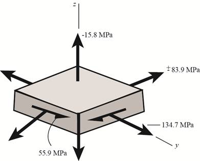
Figure (1)
Substitute
Substitute
The value of
Substitute
Thus, the factor of safety for inner radius is
Want to see more full solutions like this?
Chapter 5 Solutions
Shigley's Mechanical Engineering Design (McGraw-Hill Series in Mechanical Engineering)


- The figure shows a shaft mounted in bearings at A and D and having pulleys at B and C. The forces shown acting on the pulley surfaces represent the belt tensions. The shaft is to be made of AISI 1035 CD steel. Using distortion-energy theory with a design factor of 2, determine the minimum shaft diameter to avoid yielding.arrow_forwardA steel shaft of 75 mm diameter is pressed into a steel hub of 100 mm outside diameter and 200 mm long in such a man- ner that under an applied torque of 6 kN-m relative slip is just avoided. Find the interference fit, assuming a 75 mm common diameter, and the тахіти maximum circumferential stress in the hub. µ = 0-3, E = 210 GN/m².arrow_forwardThe gear forces shown act in planes parallel to the yz plane. The force on 20 in gear A is 300 lbf. Consider the bearings at O and B to be simple supports. For a static analysis and a factor of safety of 3.5, use both the DET and 16 in the MSST to determine the minimum safe diameter of the shaft. 10 in Consider the material to have a yield strength of 60 ksi. Gear A Solution: 24-in D. Gear C 10-in D. 20°arrow_forward
- 1- The bearings at A and B exert only y and z components of force on the shaft. If Sy = 150 MPa for the selected ductile material, determine the factor of safety if the shaft diameter is 40 mm. Use the maximum distortion-energy theory of failure. Show the following procedures through the calculation steps (Free Body diagram (FBD), Reaction at A and D, Bending moment diagram, point of max. moment, Torque diagram, draw the element showing general stress (x, Txy), the factor of safety using the MDE. 500 N 100 mm 150 mm 200 mm 150 mm 100 mm. 500 Narrow_forward. The mean diameter of the driving pulley for a vec-belt drive with two belts is 110 mm. The pulley groove angle is 40° and the drive transmits 4.4 kW at a speed of rotation of 1500 rev/min. The coefficient of frietion between belt and pulley 0.32, and the angle of lap is 160°. Determine the driving torque and the maximum stress in the belt material if the cross-sectional area of each belt is 120 mm.arrow_forwardA pulley is keyed to a shaft midway between two anti-friction bearings. The bending moment at the pulley varies from – 170 N-m to + 510 N-m.The shaft is made of cold drawn steel having an ultimate strength of 540 MPa and yield strength of 400 MPa, Take σe = 0.5 σu. Determine the required diameter for an indefinite life based on Goodman equation. The actual stress concentration factor for the keyway is 1.6. The factor of safety is 1.5. Take size factor = 0.85 and surface finish factor = 0.88.arrow_forward
- A single disc clutch with both sides effective is required for a vehicle. The power for initial estimation of the clutch is 100 kW at 4000 rpm. Determine the radial dimensions (inner and outer radius) and the actuating force (W). Base the design on the uniform wear assumption. Assume maximum pressure (pmax) as 1.6 MN/m2 and ?2?1= 1√2where ‘r2’ and ‘r1’ represent inner and outer radius of the friction surface. Take µ = 0.35. Find also the minimum pressure (pmin).arrow_forwardThe figure (attached) shows a belt pulley mechanism which is loaded statically. The shaft is made of AISI 1030 steel with the yield strength of 480 MPa. Using distortion energy theory (DET), determine the diameter of the shaft with a factor of safety of 2.arrow_forwardA hollow shaft made from AISI 4340 steel has an outer diameter D. of 4 in. and an inner diameter Di of 2.5 in. The shaft rotates at 46 rpm for one hour each day. It is supported by two bearings and loaded in the middle with a load W of 5500 lbf. The distance between the bearings Lis 78 in. The maximum tensile stress due to bending for this type of cyclic loading is calculated using the following equation: 8WLD, #(Dg – D{) What is the stress ratio for this type of cyclic loading? Would this shaft last for one year assuming a safety factor of 2?arrow_forward
- The shaft is made of A-36 steel. It has a diameter of 38 mm and is supported by bearings at A and D, which allow free rotation. The shear modulus of elasticity for A-36 steel is 75 GPa. (Figure 1) Part A Determine the angle of twist of gear C with respect to B. Express your answer using three significant figures. vec Figure 1 of 1> rad Submit Request Answer 90 N-m 0.6 m Provide Feedback Ne 90 N-m 0.75 m 0.9 marrow_forwardA 25 mm diameter shaft is made of forged steel 30C8 (Sut = 600N/mm2). There is a step in the shaft and the theoretical stressconcentration factor at the step is 2.1. The notch sensitivity factor is0.84. Determine the endurance limit of the shaft if it is subjectedto a reversed bending moment.arrow_forwardWhen drilling a well at a constant angular velocity, the bottom end of the drill pipe encounters a torsional resistance TA. Also, soil along the sides of the pipe creates a distributed frictional torque along its length, varying uniformly from zero at the surface B to tA at A. Determine the minimum torque TB that must be supplied by the drive unit to overcome the resisting torques, and calculate the maximum shear stress in the pipe. The pipe has an outer radius ro and an inner radius ri.arrow_forward
 Elements Of ElectromagneticsMechanical EngineeringISBN:9780190698614Author:Sadiku, Matthew N. O.Publisher:Oxford University Press
 Mechanics of Materials (10th Edition)Mechanical EngineeringISBN:9780134319650Author:Russell C. HibbelerPublisher:PEARSON
 Thermodynamics: An Engineering ApproachMechanical EngineeringISBN:9781259822674Author:Yunus A. Cengel Dr., Michael A. BolesPublisher:McGraw-Hill Education
 Control Systems EngineeringMechanical EngineeringISBN:9781118170519Author:Norman S. NisePublisher:WILEY
 Mechanics of Materials (MindTap Course List)Mechanical EngineeringISBN:9781337093347Author:Barry J. Goodno, James M. GerePublisher:Cengage Learning
 Engineering Mechanics: StaticsMechanical EngineeringISBN:9781118807330Author:James L. Meriam, L. G. Kraige, J. N. BoltonPublisher:WILEY