
Mechanics of Materials (10th Edition)
10th Edition
ISBN: 9780134319650
Author: Russell C. Hibbeler
Publisher: PEARSON
expand_more
expand_more
format_list_bulleted
Concept explainers
Videos
Textbook Question
Chapter 3.4, Problem 3.3P
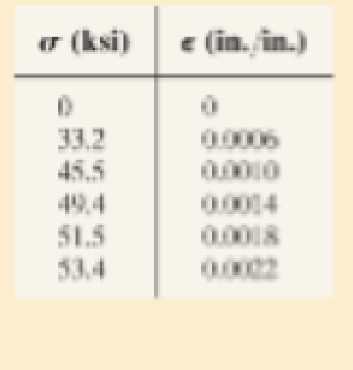
Data taken from a stress-strain test for a ceramic are given in the table. The curve is linear between the origin and the first point. Plot the diagram, and determine approximately the modulus of toughness. The fracture stress is σf = 53.4 ksi.
Expert Solution & Answer
Want to see the full answer?
Check out a sample textbook solution
Students have asked these similar questions
Tensile test specimens are extracted from the "X" and "y" directions of a rolled sheet of metal. "x" is the rolling direction, "y" is
transverse to the rolling direction, and "z" is in the thickness direction. Both specimens were pulled to a longitudinal strain =
0.15 strain. For the sample in the x-direction, the width strain was measured to be ew= -0.0923 at that instant. For the sample in
the y-direction, the width strain was measured to be gw=-0.1000 at that instant.
The yield strength of the x-direction specimen was 50 kpsi and the yield strength of the y-direction specimen was 52 kpsi.
Determine the strain ratio for the x direction tensile test specimen. Determine the strain ratio for the y-direction tensile test
specimen. Determine the expected yield strength in the z-direction. Give your answer in units of kpsi (just the number). If the
sheet is plastically deformed in equal biaxial tension (a, = 0, to the point where & = 0.15, calculate the strain, 6, that would be
expected.
Determine the change in length, width and thickness of steel bar which is 4m long, 30mm wide
and 20mm thick and is subjected to an axial pull of 30 kN in the direction of length. Take E = 200
GPa and poison's ratio of 0.3. Also determine the volumetric strain and change in volume.
The elastic portion of the tension stress–strain diagram for an aluminum alloy is shown in the figure. The specimen used for the test has a gage length of 2 in. and a diameter of 0.5 in. If the applied load is 10 kip, determine the new diameter of the specimen. The shear modulus is Gal = 3.811032 ksi.
Chapter 3 Solutions
Mechanics of Materials (10th Edition)
Ch. 3.4 - Define a homogeneous material.Ch. 3.4 - Indicate the points on the stress-strain diagram...Ch. 3.4 - Define the modulus of elasticity E.Ch. 3.4 - At room temperature, mild steel is a ductile...Ch. 3.4 - Engineering stress and strain are calculated using...Ch. 3.4 - As the temperature increases the modulus of...Ch. 3.4 - A 100-mm-long rod has a diameter of 15 mm. If an...Ch. 3.4 - A bar has a length of 8 in. and cross-sectional...Ch. 3.4 - A 10-mm-diameter rod has a modulus of elasticity...Ch. 3.4 - The material for the 50-mm-long specimen has the...
Ch. 3.4 - The material for the 50-mm-long specimen has the...Ch. 3.4 - If the elongation of wire BC is 0.2 mm after the...Ch. 3.4 - A tension test was performed on a steel specimen...Ch. 3.4 - Data taken from a stress-strain test for a ceramic...Ch. 3.4 - Data taken from a stress-strain test for a ceramic...Ch. 3.4 - The stress-strain diagram for a steel alloy having...Ch. 3.4 - The stress-strain diagram for a steel alloy having...Ch. 3.4 - The stress-strain diagram for a steel alloy having...Ch. 3.4 - The rigid beam is supported by a pin at C and an...Ch. 3.4 - The rigid beam is supported by a pin at C and an...Ch. 3.4 - Acetal plastic has a stress-strain diagram as...Ch. 3.4 - The stress-strain diagram for an aluminum alloy...Ch. 3.4 - The stress-strain diagram for an aluminum alloy...Ch. 3.4 - The stress-strain diagram for an aluminum alloy...Ch. 3.4 - A bar having a length of 5 in. and cross-sectional...Ch. 3.4 - The rigid pipe is supported by a pin at A and an...Ch. 3.4 - The rigid pipe is supported by a pin at A and an...Ch. 3.4 - Direct tension indicators are sometimes used...Ch. 3.4 - The rigid beam is supported by a pin at C and an...Ch. 3.4 - The rigid beam is supported by a pin at C and an...Ch. 3.4 - The stress-strain diagram for a bone is shown, and...Ch. 3.4 - The stress-strain diagram for a bone is shown and...Ch. 3.4 - The two bars are made of a material that has the...Ch. 3.4 - The two bars are made of a material that has the...Ch. 3.4 - The pole is supported by a pin at C and an A-36...Ch. 3.4 - The bar DA is rigid and is originally held in the...Ch. 3.7 - A 100-mm-long rod has a diameter of 15 mm. If an...Ch. 3.7 - A solid circular rod that is 600 mm long and 20 mm...Ch. 3.7 - A 20-mm-wide block is firmly bonded to rigid...Ch. 3.7 - A 20-mm-wide block is bonded to rigid plates at...Ch. 3.7 - The acrylic plastic rod is 200 mm long and 15 mm...Ch. 3.7 - The plug has a diameter of 30 mm and fits within a...Ch. 3.7 - The elastic portion of the stress-strain diagram...Ch. 3.7 - The elastic portion of the stress-strain diagram...Ch. 3.7 - The brake pads for a bicycle tire are made of...Ch. 3.7 - The lap joint is connected together using a 1.25...Ch. 3.7 - The lap joint is connected together using a 1.25...Ch. 3.7 - The rubber block is subjected to an elongation of...Ch. 3.7 - The shear stress-strain diagram for an alloy is...Ch. 3.7 - A shear spring is made from two blocks of rubber,...Ch. 3 - The elastic portion of the tension stress-strain...Ch. 3 - The elastic portion of the tension stress-strain...Ch. 3 - The rigid beam rests in the horizontal position on...Ch. 3 - The wires each have a diameter of 12 in., length...Ch. 3 - The wires each have a diameter of 12 in., length...Ch. 3 - diameter steel bolts. If the clamping force in...Ch. 3 - The stress-strain diagram for polyethylene, which...Ch. 3 - The pipe with two rigid caps attached to its ends...Ch. 3 - The 8-mm-diameter bolt is made of an aluminum...Ch. 3 - An acetal polymer block is fixed to the rigid...
Knowledge Booster


Learn more about
Need a deep-dive on the concept behind this application? Look no further. Learn more about this topic, mechanical-engineering and related others by exploring similar questions and additional content below.Similar questions
- Question 3 Determine the elongation of the square hollow bar when it is subjected to the axial force P = 100 kN, find the permanent elongation of the bar. The bar is made of a metal alloy having a stress-strain diagram which can be approximated as shown. o (MPa) 500 600 mm P 50 mm 250 5 mm e (mm/mm) 0.00125 0.05 50 mm ´5 mm a. Find the stress (MPa) of the bar. b. Find the permanent elongation (mm) of the bar.arrow_forwardThe plastic distorts as shown by the dashed lines. (Figure 1) The dimensions are L = 460 mm, H = 345 mm, d₁ = 3 mm, d₂ = 5 mm, d3 = 13 mm, d4 = 8 mm, d5 = 3 mm, and de = 6 mm. Figure H B A dz dg ds + 1 of 1 Part A Determine the shear strain Yzy at corner A. Express your answer to three significant figures and include appropriate units. ol Di μA ? (YA)zy = Value Units Submit Request Answer Part B Determine the shear strain Yzy at corner B. Express your answer to three significant figures and include appropriate units. Di μA ? (YB)Ty = Value Units Submit Provide Feedback Request Answerarrow_forwarddiagram and determine approximately the modulus of elasticity, the yield stress, the ultimate stress, and the fracture 2.00 in. The data is listed in the table. Plot the stress-strain 8-1. A tension test was performed on a steel specimen n original diameter of 0.503 in. and gage length of PROBLEMS *84. origi the f having an for t and stress. Use a scale of 1 in. Dodraw the elastic region, using the same stress scale but a 20 ksi and 1 in. = 0.05 in./in. strain scale of 1 in.= 0.001 in./in. Load (kip) Elongation (in.) 0. 0. 0.0005 0.0015 1.50 4.60 8.00 11.00 0.0025 0.0035 0.0050 11.80 11.80 0.0080 0.0200 12.00 16.60 0.0400 0.1000 0.2800 20.00 21.50 19.50 18.50 0.4000 0.4600 Prob. 8-1arrow_forward
- A stress element in a rock mass making up a slope experiences a 2D stress as follows: σx = 8 MPa, σy = 4 MPa , tauxy = 3 MPa A. By using the stress transformation equation, draw a curve of the stress variation experienced by the stress element at the axis of rotation angle θ = 0-180°. Use the interval θ = 1°, with the x-axis and stress as the y-axis. Mark on the curve where the principal stress and maximum shear stress occur. Draw the three stress curves completely and neatly B. Draw the stress element along with the magnitude and direction of the stress at the angle where the principal stress occurs and at the angle where the maximum shear stress occurs. C. Write down the direction vectors of the orientation of the principal stress (n1, and n₂) and the maximum shear stress (nmax). Write it in unit vector form i and j. D. Prove that the value of the stress invariant (I1, and I2) using the principal stress is reached and prove that the orthogonality condition of the direction cosine is…arrow_forwardA sheet of copper is stretched biaxially in the xy-plane. If the strains in the sheet are 0.40 x 10 -3 in thex direction and 0.30 x 10⁻³ in the y direction, determine the stresses in the x and y direction. Also,determine the strain in the z direction. The modulus of elastic and Poisson’s ratio of copper is 110GPa and 0.35 respectively.arrow_forwardNatural rubber is tested in tension to a maximum extension ratio of λ = 3. The Mooney-Rivlin constants for this material are found to be C1 = 0.069 MPa and C2 = 0.125 MPa. Plot the corresponding uniaxial stress vs. extension ratio behavior over the tested range. Derive an expression for the slope of the function, then determine the secant and tangent moduli at 100% strain.arrow_forward
- The strain rosette shown below was used to obtain normal strain data at a point on the free surface of a 2024-T4 aluminum alloy machine part. The gage readings were Ea = +630μ, b = +450μ, and Ec = +1200μ. Determine (a) The strain components Ex, Ey, and Yay at the point. (b) The stress components o, y, and Tay at the point. Express the stresses in SI units. (c) The principal stresses and the maximum shearing stress at the point. Gage c Y 90° Gage b Gage a 45° -Xarrow_forward2. The stress-strain diagram for a bone is shown and, according to the data analysis curve fitting tool, it can be described by the equation ε = 0.45 · 10-6 +0.36 10-12³, where stress is in kPa. Determine the modulus of toughness and the amount of elongation of a 200-mm-long region just before it fractures if failure occurs at ε = 0.12 mm/mm. -€ = 0.45(106) + 0.36(10-12)³ € ↑Parrow_forwardThe steel strip has a uniform thickness of 50 mm. Compute the elongation of the strip caused by the 500-kN axial force. The modulus of elasticity of steel is 200 GPa. 1000 mm- 1000 mm 500 kN 500 kN 50 mm -120 mm 50 mm Match each item to a choice: Choices: # 1.345 mm # 1.356 mm # 0.6725 mm #0.678 mm 1.251 mm # 0.6253 mmarrow_forward
- The principal plane stresses and associated strains in a 35 ksi, 02 = 15 ksi, plane at a point are 01 1 €1 = 1.02(10-3), 2 = 0.180(10-³). ▼ Determine the modulus of elasticity. Express your answer using three significant figures and include the appropriate units. E= Submit Part B V= μA Value Request Answer Submit Determine the Poisson's ratio. Express your answer using three significant figures. ΠΑΠΙ ΑΣΦ | Η VE Units Request Answer ? vec POSSIA space ?arrow_forward7. A 20-mm-wide block is firmly bonded to rigid plates at its top and bottom. When the force P is applied the block deforms into the shape shown by the dashed line. Determine the magnitude of P. The block's material has a modulus of rigidity of G = 26 GPa. Assume that the material does not yield and use small angle analysis. 150 mm - 0.5 mm 150 mm [Ans: P= 260 kNarrow_forwardR8-1. The elastic portion of the tension stress-strain diagram for an aluminum alloy is shown in the figure. The specimen used for the test has a gauge length of 50 mm and a diameter of 12.5 mm. When the applied load is 40 kN, the new diameter of the specimen is 12.4800 mm. Compute the shear modulus G, for the aluminum. a (MPa) 350 (mm/mm) 0.00480arrow_forward
arrow_back_ios
SEE MORE QUESTIONS
arrow_forward_ios
Recommended textbooks for you
 Elements Of ElectromagneticsMechanical EngineeringISBN:9780190698614Author:Sadiku, Matthew N. O.Publisher:Oxford University Press
 Mechanics of Materials (10th Edition)Mechanical EngineeringISBN:9780134319650Author:Russell C. HibbelerPublisher:PEARSON
 Thermodynamics: An Engineering ApproachMechanical EngineeringISBN:9781259822674Author:Yunus A. Cengel Dr., Michael A. BolesPublisher:McGraw-Hill Education
 Control Systems EngineeringMechanical EngineeringISBN:9781118170519Author:Norman S. NisePublisher:WILEY
 Mechanics of Materials (MindTap Course List)Mechanical EngineeringISBN:9781337093347Author:Barry J. Goodno, James M. GerePublisher:Cengage Learning
 Engineering Mechanics: StaticsMechanical EngineeringISBN:9781118807330Author:James L. Meriam, L. G. Kraige, J. N. BoltonPublisher:WILEY
Elements Of Electromagnetics
Mechanical Engineering
ISBN:9780190698614
Author:Sadiku, Matthew N. O.
Publisher:Oxford University Press
Mechanics of Materials (10th Edition)
Mechanical Engineering
ISBN:9780134319650
Author:Russell C. Hibbeler
Publisher:PEARSON
Thermodynamics: An Engineering Approach
Mechanical Engineering
ISBN:9781259822674
Author:Yunus A. Cengel Dr., Michael A. Boles
Publisher:McGraw-Hill Education
Control Systems Engineering
Mechanical Engineering
ISBN:9781118170519
Author:Norman S. Nise
Publisher:WILEY
Mechanics of Materials (MindTap Course List)
Mechanical Engineering
ISBN:9781337093347
Author:Barry J. Goodno, James M. Gere
Publisher:Cengage Learning
Engineering Mechanics: Statics
Mechanical Engineering
ISBN:9781118807330
Author:James L. Meriam, L. G. Kraige, J. N. Bolton
Publisher:WILEY
Strain energy and strain energy density introduced; Author: Engineer4Free;https://www.youtube.com/watch?v=m14sqLGg4BQ;License: Standard youtube license