
Mechanics of Materials (10th Edition)
10th Edition
ISBN: 9780134319650
Author: Russell C. Hibbeler
Publisher: PEARSON
expand_more
expand_more
format_list_bulleted
Videos
Textbook Question
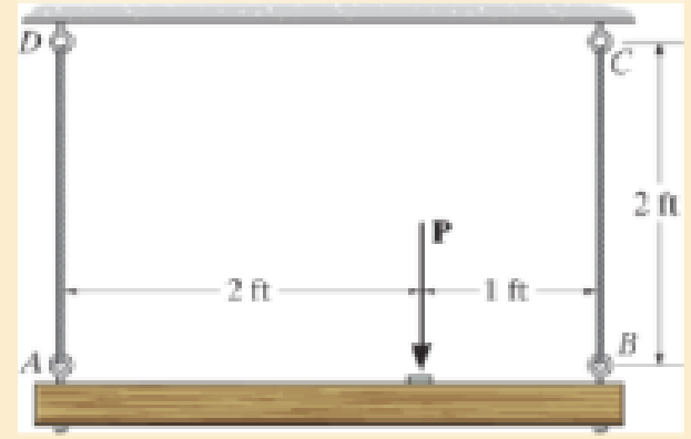
Chapter 3, Problem 3.4RP
The wires each have a diameter of
Expert Solution & Answer

Learn your wayIncludes step-by-step video

schedule05:08
Students have asked these similar questions
Find the area of cross section of the bar
The cross sectional dimensions of a beam are shown. If the flange thickness, h, is 11.7 mm, determine the second moment of area of the cross section.
Note: Give your answer in mm4
Note: Do NOT include units in your answer.
10HH
150MM
Answer:
120
hmm
The hollow square cross section shown has a wall thickness, T, of 12.0 mm. Determine the second moment of area of the cross section.
Note: Give your answer in mm²
Note: Do NOT include units in your answer
100mm
Answer:
K-T
Chapter 3 Solutions
Mechanics of Materials (10th Edition)
Ch. 3.4 - Define a homogeneous material.Ch. 3.4 - Indicate the points on the stress-strain diagram...Ch. 3.4 - Define the modulus of elasticity E.Ch. 3.4 - At room temperature, mild steel is a ductile...Ch. 3.4 - Engineering stress and strain are calculated using...Ch. 3.4 - As the temperature increases the modulus of...Ch. 3.4 - A 100-mm-long rod has a diameter of 15 mm. If an...Ch. 3.4 - A bar has a length of 8 in. and cross-sectional...Ch. 3.4 - A 10-mm-diameter rod has a modulus of elasticity...Ch. 3.4 - The material for the 50-mm-long specimen has the...
Ch. 3.4 - The material for the 50-mm-long specimen has the...Ch. 3.4 - If the elongation of wire BC is 0.2 mm after the...Ch. 3.4 - A tension test was performed on a steel specimen...Ch. 3.4 - Data taken from a stress-strain test for a ceramic...Ch. 3.4 - Data taken from a stress-strain test for a ceramic...Ch. 3.4 - The stress-strain diagram for a steel alloy having...Ch. 3.4 - The stress-strain diagram for a steel alloy having...Ch. 3.4 - The stress-strain diagram for a steel alloy having...Ch. 3.4 - The rigid beam is supported by a pin at C and an...Ch. 3.4 - The rigid beam is supported by a pin at C and an...Ch. 3.4 - Acetal plastic has a stress-strain diagram as...Ch. 3.4 - The stress-strain diagram for an aluminum alloy...Ch. 3.4 - The stress-strain diagram for an aluminum alloy...Ch. 3.4 - The stress-strain diagram for an aluminum alloy...Ch. 3.4 - A bar having a length of 5 in. and cross-sectional...Ch. 3.4 - The rigid pipe is supported by a pin at A and an...Ch. 3.4 - The rigid pipe is supported by a pin at A and an...Ch. 3.4 - Direct tension indicators are sometimes used...Ch. 3.4 - The rigid beam is supported by a pin at C and an...Ch. 3.4 - The rigid beam is supported by a pin at C and an...Ch. 3.4 - The stress-strain diagram for a bone is shown, and...Ch. 3.4 - The stress-strain diagram for a bone is shown and...Ch. 3.4 - The two bars are made of a material that has the...Ch. 3.4 - The two bars are made of a material that has the...Ch. 3.4 - The pole is supported by a pin at C and an A-36...Ch. 3.4 - The bar DA is rigid and is originally held in the...Ch. 3.7 - A 100-mm-long rod has a diameter of 15 mm. If an...Ch. 3.7 - A solid circular rod that is 600 mm long and 20 mm...Ch. 3.7 - A 20-mm-wide block is firmly bonded to rigid...Ch. 3.7 - A 20-mm-wide block is bonded to rigid plates at...Ch. 3.7 - The acrylic plastic rod is 200 mm long and 15 mm...Ch. 3.7 - The plug has a diameter of 30 mm and fits within a...Ch. 3.7 - The elastic portion of the stress-strain diagram...Ch. 3.7 - The elastic portion of the stress-strain diagram...Ch. 3.7 - The brake pads for a bicycle tire are made of...Ch. 3.7 - The lap joint is connected together using a 1.25...Ch. 3.7 - The lap joint is connected together using a 1.25...Ch. 3.7 - The rubber block is subjected to an elongation of...Ch. 3.7 - The shear stress-strain diagram for an alloy is...Ch. 3.7 - A shear spring is made from two blocks of rubber,...Ch. 3 - The elastic portion of the tension stress-strain...Ch. 3 - The elastic portion of the tension stress-strain...Ch. 3 - The rigid beam rests in the horizontal position on...Ch. 3 - The wires each have a diameter of 12 in., length...Ch. 3 - The wires each have a diameter of 12 in., length...Ch. 3 - diameter steel bolts. If the clamping force in...Ch. 3 - The stress-strain diagram for polyethylene, which...Ch. 3 - The pipe with two rigid caps attached to its ends...Ch. 3 - The 8-mm-diameter bolt is made of an aluminum...Ch. 3 - An acetal polymer block is fixed to the rigid...
Additional Engineering Textbook Solutions
Find more solutions based on key concepts
What parts are included in the vehicle chassis?
Automotive Technology: Principles, Diagnosis, And Service (6th Edition) (halderman Automotive Series)
What parts are included in the vehicle chassis?
Automotive Technology: Principles, Diagnosis, and Service (5th Edition)
A pilot weighs 150 lb and is traveling at a constant speed of 120 ft/ s. Determine the normal force he exerts o...
Engineering Mechanics: Dynamics (14th Edition)
ICA 2-1
For each of the following situations, indicate whether you think the action is ethical or unethical or ...
Thinking Like an Engineer: An Active Learning Approach (4th Edition)
In each case, construct the parallelogram law to show FR = F1 + F2. Then establish the triangle rule, where FR ...
Statics and Mechanics of Materials (5th Edition)
Two couples act on the beam. If F = 125 lb, determine the resultant couple moment.
Engineering Mechanics: Statics
Knowledge Booster


Learn more about
Need a deep-dive on the concept behind this application? Look no further. Learn more about this topic, mechanical-engineering and related others by exploring similar questions and additional content below.Similar questions
- Determine the vertical displacement of point B. Each A-36 steel member has a cross- sectional area of 400 mm². Using Castigliano's Theorem. 30 kN -1.5 m- B 20 kN -1.5 m Figure 1 2marrow_forwardThe cross sectional dimensions of a beam are shown. If the flange thickness, h, is 16.2 mm, determine the second moment of area of the cross section. Note: Give your answer in mm4 Note: Do NOT include units in your answer. 10MM 150HM 120 MM hmmarrow_forwardIf a solid shaft has a diameter of 4 inches. Determine the polar section modulusarrow_forward
- A plate and angle column is composed of 4 angle bars in equal sizes, 2 plates and 1 web at the middle. Determine the values of Ix from the bottom.arrow_forwardUsing singularity functions, determine the expressions of V (cutting force) and M (deflector moment) on each stretch of the beam schematized below and construct the diagrams of cutting force and deflector moment. Take the z-axis starting with point A and heading toward B. Stretch I: 0 ≤ z < 1; Stretch II: 1 ≤ z < 4; Stretch III: 4 ≤ z ≤ 5.arrow_forwardFor the H – section shown, Find the value of h so that Ix = Iy.arrow_forward
- Determine the distance that end A of the rigid bar moves downward, if end C moves upward by 0.06 in.arrow_forwardDetermine the location y¯y¯ of the centroidal axis x¯−x¯x¯−x¯ of the beam's cross-sectional area. Neglect the size of the corner welds at AA and BB for the calculation. Take rrr = 66 mmmm .arrow_forwardL-length steel with a diameter at the wide end, twice the diameter at the narrow end determine the X and y coordinates of the center of mass of the bar in L. (The density of steel material is constant).arrow_forward
- Question 1: Given that Tuitow = 50 MPa for the rod AB and tattow = 25 MPa for the rod BC. If T=1250 N.m, find the required radius for both rods. Ahmtmum AB = BC =arrow_forward3. At temperature T₁, the two rigidly connected rods just fit the rigid supports. If both sections are identical except for the diameter, prove that the following equations are true when temperature rises to T₂. a. F= b. OAB C. OBC A x(T₂-T₁)лd²E 20 x(T₂-T₁)E 5 9x(T₂-T₁)E 5 -1/2- d B 1/12- d Carrow_forwardDetermine the magnitude of the vertical force Cy for the cantilever beam, where P = 29 kips and M = 40 kip-ft. A 3.5 ft O 21 kips O 25 kips 42 kips 18 kips 29 kips M B 6.5 ftarrow_forward
arrow_back_ios
SEE MORE QUESTIONS
arrow_forward_ios
Recommended textbooks for you
 Elements Of ElectromagneticsMechanical EngineeringISBN:9780190698614Author:Sadiku, Matthew N. O.Publisher:Oxford University Press
 Mechanics of Materials (10th Edition)Mechanical EngineeringISBN:9780134319650Author:Russell C. HibbelerPublisher:PEARSON
 Thermodynamics: An Engineering ApproachMechanical EngineeringISBN:9781259822674Author:Yunus A. Cengel Dr., Michael A. BolesPublisher:McGraw-Hill Education
 Control Systems EngineeringMechanical EngineeringISBN:9781118170519Author:Norman S. NisePublisher:WILEY
 Mechanics of Materials (MindTap Course List)Mechanical EngineeringISBN:9781337093347Author:Barry J. Goodno, James M. GerePublisher:Cengage Learning
 Engineering Mechanics: StaticsMechanical EngineeringISBN:9781118807330Author:James L. Meriam, L. G. Kraige, J. N. BoltonPublisher:WILEY
Elements Of Electromagnetics
Mechanical Engineering
ISBN:9780190698614
Author:Sadiku, Matthew N. O.
Publisher:Oxford University Press
Mechanics of Materials (10th Edition)
Mechanical Engineering
ISBN:9780134319650
Author:Russell C. Hibbeler
Publisher:PEARSON
Thermodynamics: An Engineering Approach
Mechanical Engineering
ISBN:9781259822674
Author:Yunus A. Cengel Dr., Michael A. Boles
Publisher:McGraw-Hill Education
Control Systems Engineering
Mechanical Engineering
ISBN:9781118170519
Author:Norman S. Nise
Publisher:WILEY
Mechanics of Materials (MindTap Course List)
Mechanical Engineering
ISBN:9781337093347
Author:Barry J. Goodno, James M. Gere
Publisher:Cengage Learning
Engineering Mechanics: Statics
Mechanical Engineering
ISBN:9781118807330
Author:James L. Meriam, L. G. Kraige, J. N. Bolton
Publisher:WILEY
How to balance a see saw using moments example problem; Author: Engineer4Free;https://www.youtube.com/watch?v=d7tX37j-iHU;License: Standard Youtube License