
Videos
(a)
The expression for the total energy that dissipated by the resistor in one time constant.
(a)
Answer to Problem 17PQ
The expression for the total energy that dissipated by the resistor in one time constant is,
Explanation of Solution
The following figure shows the given diagram-
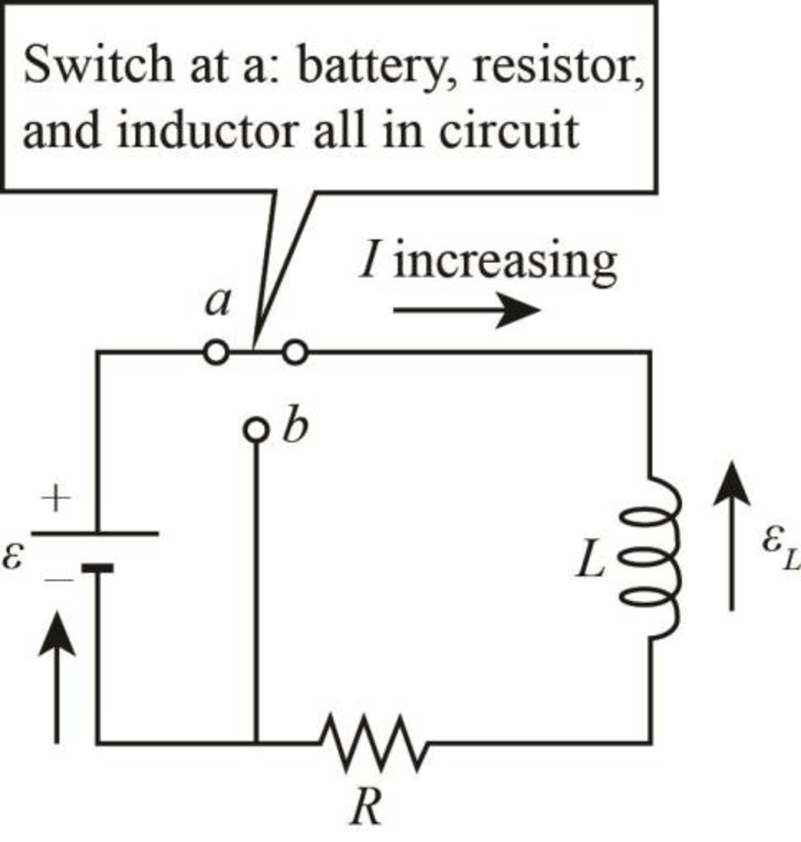
Figure-(1)
Here,
Write the expression for current pass through the resistor.
Here,
Write the expression for power dissipated in the resistor as function of time.
Here,
Substitute
Write the expression for energy dissipated
Substitute
Integrate the above expression between the limits
Conclusion:
Therefore, the expression for the total energy that dissipated by the resistor in one time constant is
(b)
The expression for the total charge that passes through the resistor in one time constant.
(b)
Answer to Problem 17PQ
The expression for the total charge that passes through the resistor in one time constant is,
Explanation of Solution
Write the expression for decaying current.
Write the expression for power dissipated in the resistor as function of time.
Substitute
Integrate the above expression between the limits
Conclusion:
Therefore, the expression for the total energy that dissipated by the resistor in one time constant is,
(c)
The comparison between the above two results and comment.
(c)
Answer to Problem 17PQ
The energy dissipated in the resistor when the current decays is more than the energy dissipated when the current grows in the circuit.
Explanation of Solution
Write the expression for energy growth that dissipated through the resistor.
Here,
Write the expression for energy decay that dissipated through the resistor.
Here,
Take the ratio of both equations.
Conclusion:
Substitute
Therefore, the energy dissipated in the resistor when the current decays is more than the energy dissipated when the current grows in the circuit.
Want to see more full solutions like this?
Chapter 33 Solutions
Physics for Scientists and Engineers: Foundations and Connections


- In Figure 33.9A (page 1052), the switch is closed at a at t = 0. Find an expression for the power dissipated by the resistor as a function of time, and sketch your result. Is the power lost greater as soon as the switch is closed or a long time after it has been closed? Does your answer make sense?arrow_forwardEach of the three situations in Figure P32.68 shows a resistor in a circuit in which currents are induced. Using Lenzs law, determine whether the current in each situation is from a to b or from b to a. a. If the current I in the wire in Figure P32.68A is increased from zero to I, what is the direction of the current induced across the resistor R? b. The switch in Figure P32.68B is initially closed and is thrown open at t = 0. What is the direction of the current induced across the resistor R immediately afterward? c. A bar magnet is brought close to the circuit shown in Figure P32.68C. What is the direction of the current induced across the resistor R?arrow_forwardIn the circuit of Figure P27.25, the switch S has been open for a long time. It is then suddenly closed. Determine the time constant (a) before the switch is closed and (b) after the switch is closed. (c) Let the switch be closed at t = 0. Determine the current in the switch as a function of time. Figure P27.25 Problems 25 and 26.arrow_forward
- A 210.0- resistor and an initially uncharged 6.00-F capacitor are connected in series to a 12.0-V emf source. A switch is closed to complete the circuit at t = 0. a. What is the time constant of this circuit? b. What is the maximum charge on the capacitor? c. What is the charge on the capacitor at t = 3?arrow_forwardFigure P29.84 shows a circuit that consists of two identical emf devices. If R1 = R2 = R and the switch is closed, find an expression (in terms of R and ) for the current I that is in the branch from point a to b.arrow_forwardIn the circuit of Figure P27.25, the switch S has been open for a long time. It is then suddenly closed. Take = 10.0 V, R1 = 50.0 k, R2 = 100 k, and C = 10.0 F. Determine the time constant (a) before the switch is closed and (b) after the switch is closed. (c) Let the switch be closed at t = 0. Determine the current in the switch as a function of time. Figure P27.25 Problems 25 and 26.arrow_forward
- (a) What is the average power output of a heart defibrillator that dissipates 400 J of energy in 10.0 ms? (b) Considering the high-power output, why doesn’t the defibrillator produce serious bums?arrow_forwardYour team has used a data logger with graphing software to take data on the voltage across the capacitor in the series RLC circuit in the figures below. The switch is set first to position a, and the capacitor is charged. The switch is thrown to position b and oscillations begin. a S + C a Switch S has been at position a for a very long time and is then thrown to position b. You know that the capacitance C is 20.0 µF. Your data logger makes a graph of the voltage across the capacitor as a function of time, with t = 0 being the instant the switch was thrown to position b. The graph is shown in the figures below. AV (V) 30 25 20 15 10 5 t (ms) 45 50 -5 -10 -15 -20 -25 -30 Using the graph, discuss this situation in your group and determine the emf of the battery, the inductance L, and the resistance R. (a) the emf of the battery (in V) 30 V (b) the inductance L (in H) X H (c) the resistance R (in 0) llarrow_forwardA rectangular metal loop with 0.050Ω resistance is placed next to one wire of the RC circuit shown in the figure. The capacitor is charged to 20V with the polarity shown, then the switch is closed at t = 0s. What is the direction of current in the loop for t > 0s? What is the current in the loop at t = 5.0μs? Assume that only the circuit wire next to the loop is close enough to produce a significant magnetic field.arrow_forward
- A resistor, an uncharged capacitor, a dc voltage source, and an open switch are all connected in series. The switch is closed at time t = 0 s. What is the charge on the capacitor after two time constants compared to the maximum charge?arrow_forwardTina the ballarina has this RC circuit she made for school help her figure out the following a. What is the time constant for the RC circuit? b. After how long does the capacitor become 80% charged? c. How much current flows in the R3 resistor at this time? + S I R₁ R₂ C R3 www.h R₁=100 kn R₁-200 kn R₂=300kn C=5.00 μF {=9.00V THE CAPACITOR IS INNITIALY CHARGED WHEN THE SWITCH IS CLOSEDarrow_forwardPROBLEM 3: Four resistors, R, = 100 N, R2 = 250 N, R3 = 350 N and R4 = 200 N are connected such that the parallel combination of R, and R2 is connected in series with the parallel combination of | R3 and R4. The series-parallel combination is then connected across a 24 V DC power supply. A. Draw the schematic diagram and label the circuit elements. B. Calculate the equivalent resistance of the circuit. (Ans. Reg = 198. 7013 N) C. Find the total current of the circuit, the voltage across each resistor and the current through each resistor. Ans: (I, = 0. 1208 A, V1 = V2 = 8. 6275 V, V3 = V4 = 15.3725 V, I, = 0. 0863 A, I2 = 0.0345 A, I3 = 0. 0439 A, I4 = 0. 0769 A) %3D %3Darrow_forward
 Physics for Scientists and Engineers: Foundations...PhysicsISBN:9781133939146Author:Katz, Debora M.Publisher:Cengage Learning
 Physics for Scientists and Engineers with Modern ...PhysicsISBN:9781337553292Author:Raymond A. Serway, John W. JewettPublisher:Cengage Learning
 Physics for Scientists and EngineersPhysicsISBN:9781337553278Author:Raymond A. Serway, John W. JewettPublisher:Cengage Learning
 Principles of Physics: A Calculus-Based TextPhysicsISBN:9781133104261Author:Raymond A. Serway, John W. JewettPublisher:Cengage Learning