
Concept explainers
Videos
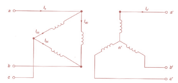
Consider three ideal single-phase transformers (with a voltage gain of
(a) Would such relationships hold for the line voltages as well?
(b) Looking into the current relationships, express
(C) Let

Trending nowThis is a popular solution!

Chapter 3 Solutions
Power System Analysis and Design (MindTap Course List)


- Consider a single-phase electric system shown in Figure 3.33. Transformers are rated as follows: XY15MVA,13.8/138kV, leakage reactance 10 YZ15MVA,138/69kV, leakage reactance 8 With the base in circuit Y chosen as 15MVA,138kV determine the per-unit impedance of the 500 resistive load in circuit Z, referred to circuits Z, Y, and X. Neglecting magnetizing currents, transformer resistances, and line impedances, draw the impedance diagram in per unit.arrow_forwardConsider Figure 3.25 of the text for a transformer with off-nominal turns ratio. (i) The per-unit equivalent circuit shown in part (c) contains an ideal transformer which cannot be accommodated by some computer programs. (a) True (b) False (ii) In the - circuit representation for real c in part (d), the admittance parameters Y11 and Y12 would be unequal. (a) True (b) False (iii) For complex c, can the admittance parameters be synthesized with a passive RLC circuit? (a) Yes (b) Noarrow_forwardConsider the single-Line diagram of a power system shown in Figure 3.42 with equipment ratings given: Generator G1: 50MVA,13.2kV,x=0.15p.u. Generator G2: 20MVA,13.8kV,x=0.15p.u. Three-phase -Y transformer T1: 80MVA,13.2/165YkV,X=0.1p.u. Three-phase Y- transformer T2: 40MVA,165Y/13.8kV,X=0.1p.u. Load: 40MVA,0.8PFlagging,operatingat150kV Choose a base of 100 MVA for the system and 132-kV base in the transmission-line circuit. Let the load be modeled as a parallel combination of resistance and inductance. Neglect transformer phase shifts. Draw a per-phase equivalent circuit of the system showing all impedances in per unit.arrow_forward
- In developing per-unit equivalent circuits for three-phase transformers. under balanced three-phase operation. (i) A common Sbase is selected for both the H and X terminals. (ii) The ratio of the voltage bases Vbase/VbaseX is selected to be equal to the ratio of the rated line-to-line voltages VratedHLL/VratedXLL. (a) Only one of the above is true. (b) Neither is true. (C) Both statements are true.arrow_forwardConsider the single-line diagram of the power system shown in Figure 3.38. Equipment ratings are Generator 1: 1000MVA,18kV,X=0.2perunit Generator 2: 1000MVA,18kV,X=0.2p.u. Synchronous motor 3: 1500MVA,20kV,X=0.2p.u. Three-phase -Y transformers T1,T2,T3,T4,: 1000MVA,500kV,Y/20kV,X=0.1p.u. Three-phase YY transformer T5: 1500MVA,500kV,Y/20kVY,X=0.1p.u. Neglecting resistance, transformer phase shift, and magnetizing reactance, draw the equivalent reactance diagram. Use a base of 100 MA and 500 kV for the 50-ohm line. Determine the per-unit reactances.arrow_forwardReconsider Problem 3.64 with the change that now Tb includes both a transformer of the same turns ratio as Ta and a regulating transformer with a 4 phase shift. On the base of Ta, the impedance of the two comp onents of Tb is jO.1 per unit. Determine the complex power in per unit transmitted to the load through each transformer. Comment on how the transformers share the real and reactive pors.arrow_forward
- An infinite bus, which is a constant voltage source, is connected to the primary of the three-winding transformer of Problem 3.53. A 7.5-MVA,13.2-kV synchronous motor with a sub transient reactance of 0.2 per unit is connected to the transformer secondary. A5-MW,2.3-kV three-phase resistive load is connected to the tertiary Choosing a base of 66 kV and 15 MVA in the primary, draw the impedance diagram of the system showing per-unit impedances. Neglect transformer exciting current, phase shifts, and all resistances except the resistive load.arrow_forwardIn developing per-unit circuits of systems such as the one shown in Figure 3.10. when moving across a transformer, the voltage base is changed in proportion to the transformer voltage ratings. (a) True (b) Falsearrow_forwardThe efficiency of a 20 kVA 15.4 / 0.4 kV three-phase power transformer is 74,1% for a load with unity power factor at rated power. Relative short circuit voltage% Uk = 30.0 and relative no-load current% I0 = 30. Since the transformer (Star-delta) is connected; Note: In 3-phase electrical machines, the current-voltage information given on the label is always line values. Phase valueWhen given, it must be specified separately. Therefore, all current-voltage information given in the question are line values. 1-) Draw the primary reduced equivalent circuit. 2-) What is the power value measured in the short circuit test of this transformer? 3-) What is the iron loss value of this transformer ?arrow_forward
- For transformers ratings are always given in kVA, not in kW because 1-It is conventional 2-Power factor of load is not known 3-For higher efficiency 4-To make calculation simplearrow_forwardSUBJECT: Elements of Electrical Machines DesignINSTRUCTIONS: - Please write clearly and understandable way. - Write all the corresponding Given with their corresponding symbols and units. - Draw/Illustrate the diagram/circuit or drawings that is related to the problem, IF POSSIBLE, which is HIGHLY REQUIRED. - Solve in step-by-step, no shortcut - Underline twice the Final Answer.PROBLEM: In connecting ideal single-phase transformers in parallel, how will the load be shared if the two transformers have different VA rating?arrow_forwardThe statement given in which option related to transformers is wrong.A) Power transformers are used as step-down transformers in step-up consumption centers in production centers. B) Current transformers for measuring current at high voltageVoltage transformers are used to measure voltage. C) Voltage adjustment can be made with the on-load tap changing feature of power transformers. D) Transformers are of great importance in reducing power losses by increasing the power value in energy transmission. E) If there is no reactive power in energy transmission with direct current, the transformer cannot be used.arrow_forward
 Power System Analysis and Design (MindTap Course ...Electrical EngineeringISBN:9781305632134Author:J. Duncan Glover, Thomas Overbye, Mulukutla S. SarmaPublisher:Cengage Learning