
Concept explainers
Videos
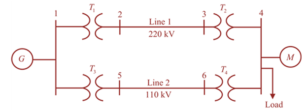
Figure 3.32 shows the oneline diagram of a three-phase power system. By selecting a common base of 100 MVA and 22 kV on the generator side, draw an impedance diagram showing all impedances including the load impedance in per-unit. The data are given a follows:
Lines I and 2 have series reactance’s of 48.4 and

Trending nowThis is a popular solution!

Chapter 3 Solutions
Power System Analysis and Design (MindTap Course List)


- Consider a single-phase electric system shown in Figure 3.33. Transformers are rated as follows: XY15MVA,13.8/138kV, leakage reactance 10 YZ15MVA,138/69kV, leakage reactance 8 With the base in circuit Y chosen as 15MVA,138kV determine the per-unit impedance of the 500 resistive load in circuit Z, referred to circuits Z, Y, and X. Neglecting magnetizing currents, transformer resistances, and line impedances, draw the impedance diagram in per unit.arrow_forwardDetermine the positive- and negative-sequence phase shifts for the three- phase transformers shown in Figure 3.36.arrow_forwardConsider three ideal single-phase transformers (with a voltage gain of ) put together as three-phase bank as shown in Figure 3.35. Assuming positive-sequence voltages for Va,Vb, and Vc find Va,Vb, and VC. in terms of Va,Vb, and Vc, respectively. (a) Would such relationships hold for the line voltages as well? (b) Looking into the current relationships, express IaIb and Ic in terms of IaIb and Ic respectively. (C) Let S and S be the per-phase complex power output and input. respectively. Find S in terms of S.arrow_forward
- Consider the single-Line diagram of a power system shown in Figure 3.42 with equipment ratings given: Generator G1: 50MVA,13.2kV,x=0.15p.u. Generator G2: 20MVA,13.8kV,x=0.15p.u. Three-phase -Y transformer T1: 80MVA,13.2/165YkV,X=0.1p.u. Three-phase Y- transformer T2: 40MVA,165Y/13.8kV,X=0.1p.u. Load: 40MVA,0.8PFlagging,operatingat150kV Choose a base of 100 MVA for the system and 132-kV base in the transmission-line circuit. Let the load be modeled as a parallel combination of resistance and inductance. Neglect transformer phase shifts. Draw a per-phase equivalent circuit of the system showing all impedances in per unit.arrow_forward2) The one-line diagram of a three-phase power system is as shown in Figure. Impedance are marked in per-unit on a 100-MVA, 400-kV base. The load at bus 2 is S2=15.93 MW - j33.4 Mvar, and at bus 3 is S3-77 MW + j14 Mvar. It is required to hold the voltage at bus 3 at ...L0 kV. Working in per-unit, determine the voltage at buses 2 and 1. (Please determine the voltage magnitude within the specified limits: 410-450 V. By considering the voltage magnitude value you determined yourself, solve the question.) V₁ j0.5 pu V₂ j0.4 pu S₂ Figure V3 S3arrow_forwardQ2) A 13.2-kV single-phase generator supplies power to a load through a transmission line. The load's impedance is Zload = 500 236.87° ohm, and the transmission line's impedance is Zline = 60 253.1° ohm. To reduce transmission line losses to 0.0103 of its losses without using the transformers design and use two transformers T1 between the generator and the transmission line and T2 between the transmission line and the load.arrow_forward
- Connect three single-phase transformers in Y-Y, with subtractive polarity, so that the line-to-line voltages on the primary are 30 degrees delayed to their respective line-to-line voltages on the secondary. It should show each step that is needed to make this connection (example: the phasor diagram) and should show the final connection of the three transformers including the polarity markings. Assume phase A on the primary is terminal "H1".arrow_forwardWhat is the main direct cause of reactive power in AC system?A. Resistance of transmission linesB. Inductance and capacitance in the loadsC. Ideal transformer connected in the systemD. Power produced by generatorarrow_forwardThe one-line diagram of a three-phase system is shown in Figure 1. By selecting a common based of 90 MVA and 32.75 kV on the generator bus, all impedances including the load impedance in per-unit are as follows: XG (new) = j0.1421 p.u XT1 (new) = j0.1219 p.u XT2 (new) = j0.1219 p.u ZOH = 0.0016 +j 0.0083 p.u Хм пеw) 3D j0.247 р.u ZLoad = 2.2759+ j1.2306 p.u T1 T2 90 MVA Motor 90 MVA 55 MVA 33/275 kV 275/11kV 10.95 kV XT=12% Xr3=12% Xx=15% Generator 95 MVA M 32.75 kV Xg=15% 2 x OH Line 138 km R = 0.01 ohm/km X = 0.05 ohm/km Load 35 MVA 10.95 kV 0.88 pf lagging Figure 1 Note: Region 1 = Generator bus Region 2 = Transmission Lines busses Region 3 = Load Bus If the motor operates at full load 0.88 power factor lagging at a terminal voltage 10.95 kV, determine the voltage at the generator bus bar.arrow_forward
- Q2) A 13.2-kV single-phase generator supplies power to a load through a transmission line. The load's impedance is Ztoad 500 236.87° ohm , and the transmission line's impedance is Zine = 60 253.1° ohm. To reduce transmission line losses to 0.0103 of its losses without using the transformers design and use two transformers T1 between the generator and the transmission line and T2 between the transmission line and the load.arrow_forwardWhat is the main direct cause of reactive power in AC system?A. Resistance of transmission linesB. Inductance and capacitance in the loadsC. Ideal transformer connected in the systemD. Power produced by generator2. “Reactive power in a system is dissipated generally as thermal energy?”A. TRUEB. FALSE3. Which of the following statements are correct for three phase circuit:A. Sum of all the three phase currents is zero in unbalanced networkB. Total power transfer to load is constant with timeC. Neutral conductor is same size in terms of material used as in single phase conductorsD. Net apparent power consumed is equal to real powerarrow_forward1. A single-phase power system as shown in Figure 1 consists of a 240 V, 60 Hz generator supplying a load, Zod = 8 + j6 Q through a transmission line of impedance, Zne = 0.08 + j0.14 Q. Answer the following questions: (1) transformer, T; and T2. Determine the voltage at the load and transmission line losses without the (ii) Determine the voltage at the load and transmission line losses with the transformer, T, and T2. T1 T2 1:10 10:1 IG Zaine Zioad source Figure 1arrow_forward
 Power System Analysis and Design (MindTap Course ...Electrical EngineeringISBN:9781305632134Author:J. Duncan Glover, Thomas Overbye, Mulukutla S. SarmaPublisher:Cengage Learning