
Mechanics of Materials (MindTap Course List)
9th Edition
ISBN: 9781337093347
Author: Barry J. Goodno, James M. Gere
Publisher: Cengage Learning
expand_more
expand_more
format_list_bulleted
Videos
Textbook Question
Chapter 2, Problem 2.5.6P
A beam is constructed using two angle sections (L 102 × 76 × 6.4) arranged back to back, as shown in the figure. The beam is fixed al joint A and attached to an elastic support having a spring constant k = l750 kN/m al joint B. Assume only the beam is subjected to temperature increase AT = 45°C. Calculate the thermal stress developed in the beam and the displacement at point B. Assume that a = 12 X 10-6/?. Let E = 205 GPa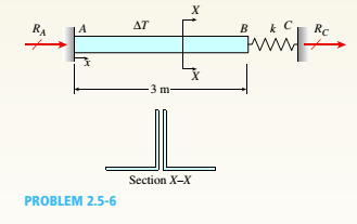
Expert Solution & Answer

Trending nowThis is a popular solution!

Chapter 2 Solutions
Mechanics of Materials (MindTap Course List)
Ch. 2 - A 10-ft rigid bar AB is supported with a vertical...Ch. 2 - Rigid bar ABC is supported with a pin at A and an...Ch. 2 - The L-shaped arm ABCD shown in the figure lies in...Ch. 2 - A steel cable with a nominal diameter of 25 mm...Ch. 2 - A steel wire- and an aluminum allay wire have...Ch. 2 - By what distance h does the cage shown in the...Ch. 2 - Rigid bar ACB is supported by an elastic circular...Ch. 2 - A plastic cylinder is held snugly between a rigid...Ch. 2 - A safety valve on the top of a tank containing...Ch. 2 - The device shown in the figure consists of a...
Ch. 2 - A small lab scale has a rigid L-shaped frame ABC...Ch. 2 - A small lab scale has a rigid L-shaped frame ABC...Ch. 2 - Two rigid bars are connected to each other by two...Ch. 2 - The three-bar truss ABC shown in the figure part a...Ch. 2 - An aluminum wire having a diameter d = 1/10 in....Ch. 2 - A uniform bar AB of weight W = 25 N is supported...Ch. 2 - A hollow, circular, cast-iron pipe (Ec =12,000...Ch. 2 - The horizon Lai rigid beam A BCD is supported by...Ch. 2 - Two pipe columns (AB, FC) are pin-connected to a...Ch. 2 - A framework ABC consists of two rigid bars AB and...Ch. 2 - Solve the preceding problem for the following...Ch. 2 - The length of the end segments of the bar (see...Ch. 2 - A long, rectangular copper bar under a tensile...Ch. 2 - An aluminum bar AD (see figure) has a...Ch. 2 - A vertical bar consists of three prismatic...Ch. 2 - A vertical bar is loaded with axial loads at...Ch. 2 - Repeat Problem 2.3-4, but now include the weight...Ch. 2 - -7 Repeat Problem 2.3-5, but n include the weight...Ch. 2 - A rectangular bar of length L has a slot in the...Ch. 2 - Solve the preceding problem if the axial stress in...Ch. 2 - A two-story building has steel columns AB in the...Ch. 2 - A steel bar is 8.0 Ft long and has a circular...Ch. 2 - A bar ABC of length L consists of two parts of...Ch. 2 - A woodpile, driven into the earth, supports a load...Ch. 2 - Consider the copper lubes joined in the strength...Ch. 2 - The nonprismalic cantilever circular bar shown has...Ch. 2 - *16 A prismatic bar AB of length L,...Ch. 2 - A flat bar of rectangular cross section, length L,...Ch. 2 - A flat brass bar has length L, constant thickness...Ch. 2 - Repeat Problem 2.3-18, but assume that the bar is...Ch. 2 - Repeat Problem 2.3-18, but assume that the bar is...Ch. 2 - A slightly tapered bar AB of solid circular crass...Ch. 2 - A circular aluminum alloy bar of length L = 1.8 m...Ch. 2 - A long, slender bar in the shape of a right...Ch. 2 - A post AB supporting equipment in a laboratory is...Ch. 2 - The main cables of a suspension bridge (see figure...Ch. 2 - A uniformly tapered lube AB of circular cross...Ch. 2 - A vertical steel bar ABC is pin-supported at its...Ch. 2 - A T-frame structure is torn posed of a prismatic...Ch. 2 - A T-frame structure is composed of prismatic beam...Ch. 2 - Repeat Problem 2.3-29 if vertical load P at D is...Ch. 2 - A bar ABC revolves in a horizontal plane about a...Ch. 2 - The assembly shown in the figure consists of a...Ch. 2 - A cylindrical assembly consisting of a brass core...Ch. 2 - A steel bar with a uniform cross section, is fixed...Ch. 2 - A horizontal rigid bar ABC is pinned at end A and...Ch. 2 - A solid circular steel cylinder S is encased in a...Ch. 2 - Three prismatic bars, two of material A and one of...Ch. 2 - A circular bar ACB of a diameter d having a...Ch. 2 - Bar ABC is fixed at both ends (see figure) and has...Ch. 2 - Repeat Problem 2.4-8, but assume that the bar is...Ch. 2 - A plastic rod AB of length L = 0.5 m has a...Ch. 2 - 2.4-11 Three steel cables jointly support a load...Ch. 2 - The fixed-end bar ABCD consists of three prismatic...Ch. 2 - A lube structure is acted on by loads at B and D,...Ch. 2 - A hollow circular pipe (see figure} support s a...Ch. 2 - The aluminum and steel pipes shown in the figure...Ch. 2 - A rigid bar of weight W = SOO N hangs from three...Ch. 2 - A bimetallic bar (or composite bar) of square...Ch. 2 - S Three-bar truss ABC (see figure) is constructed...Ch. 2 - A horizontal rigid bar of weight If' = 72001b is...Ch. 2 - A rigid bar ABCD is pinned at point B and...Ch. 2 - A rigid bar AB if of a length B = 66 in. is....Ch. 2 - Find expressions For all support reaction forces...Ch. 2 - A trimetallic bar is uniformly compressed by an...Ch. 2 - Find expressions for all support reaction Forces...Ch. 2 - The rails of a railroad track are welded together...Ch. 2 - A circular steel rod of diameter d is subjected to...Ch. 2 - A rigid bar of weight W = 750 lb hangs from three...Ch. 2 - A steel rod. of 15-mm diameter is held snugly (but...Ch. 2 - A bar AB of length L is held between rigid...Ch. 2 - A beam is constructed using two angle sections (L...Ch. 2 - A W 8 × 28 beam of a length 10 ft is held between...Ch. 2 - A plastic bar ACB having two different solid...Ch. 2 - ,5-9 A flat aluminum alloy bar is fixed at both...Ch. 2 - Repeat Problem 2.5-9 for the flat bar shown in the...Ch. 2 - A circular steel rod AB? (diameter d, = 1.0 in.,...Ch. 2 - A circular, aluminum alloy bar of a length L = 1.8...Ch. 2 - Rectangular bars of copper and aluminum are held...Ch. 2 - A brass sleeve S is fitted over a steel bolt B...Ch. 2 - A rigid triangular frame is pivoted at C and held...Ch. 2 - ,5-16 A rigid bar ABCD is pinned at end A and...Ch. 2 - A copper bar AB with a length 25 in. and diameter...Ch. 2 - A steel wire AB is stretched between rigid...Ch. 2 - -19 The mechanical assembly shown in the figure...Ch. 2 - A bar AB having a length L and axial rigidity EA...Ch. 2 - Pipe 2 has been inserted snugly into Pipe I. but...Ch. 2 - A non prism elk- bar ABC made up of segments...Ch. 2 - Wires B and C are attached to a support at the...Ch. 2 - A rigid steel plate is supported by three posts of...Ch. 2 - A capped cast-iron pipe is compressed by a brass...Ch. 2 - A plastic cylinder is held snugly between a rigid...Ch. 2 - Prob. 2.5.27PCh. 2 - Consider the sleeve made From two copper tubes...Ch. 2 - A polyethylene tube (length L) has a cap that when...Ch. 2 - Prestressed concrete beams are sometimes...Ch. 2 - Prob. 2.5.31PCh. 2 - A steel bar of rectangular cross section (1.5 in....Ch. 2 - A circular steel rod of diameter d is subjected to...Ch. 2 - A standard brick (dimensions 8 in. × 4 in. × 2.5...Ch. 2 - A brass wire of diameter d = 2.42 mm is stretched...Ch. 2 - Prob. 2.6.5PCh. 2 - A steel bar with a diameter d = 12 mm is subjected...Ch. 2 - During a tension lest of a mild-steel specimen...Ch. 2 - A copper bar with a rectangular cross section is...Ch. 2 - A prismatic bar with a length L = 3 ft and...Ch. 2 - A prismatic bar with a length L = 1 m and...Ch. 2 - The plane truss in the figure is assembled From...Ch. 2 - Plastic bar of diameter d = 32 mm is compressed in...Ch. 2 - A plastic bar of rectangular cross section (ft =...Ch. 2 - A copper bar of rectangular cross section (b = 18...Ch. 2 - A circular brass bar with a diameter J is member...Ch. 2 - Two boards are joined by gluing along a scarf...Ch. 2 - Acting on the sides of a stress element cut from a...Ch. 2 - A prismatic bar is subjected to an axial force...Ch. 2 - The normal stress on plane pq of a prismatic bar...Ch. 2 - A tension member is to be constructed of two...Ch. 2 - -21 Plastic bar AB of rectangular cross section (6...Ch. 2 - A compression bar having a square cross section...Ch. 2 - A prismatic bar AD of length L, cross-sectional...Ch. 2 - A bar with a circular cross section having two...Ch. 2 - A three-story steel column in a building supports...Ch. 2 - The bar ABC shown in the figure is loaded by a...Ch. 2 - Determine the strain energy per unit volume (units...Ch. 2 - The truss ABC shown in the Figure is subjected to...Ch. 2 - -7 The truss A BC Shawn in the figure supports a...Ch. 2 - The statically indeterminate structure shown in...Ch. 2 - A slightly tapered bar AB of rectangular cross...Ch. 2 - A compressive load P is transmitted through a...Ch. 2 - A block B is pushed against three springs by a...Ch. 2 - A bungee cord that behaves linearly elastically...Ch. 2 - A sliding collar of weight W = 150 lb falls From a...Ch. 2 - Solve the preceding problem if the collar has mass...Ch. 2 - Prob. 2.8.3PCh. 2 - A block weighing W = 5.0 N drops inside a cylinder...Ch. 2 - Solve the preceding problem for W = 1.0 lb. h = 12...Ch. 2 - Prob. 2.8.6PCh. 2 - A weight W = 4500 lb falls from a height h onto a...Ch. 2 - Prob. 2.8.8PCh. 2 - Prob. 2.8.9PCh. 2 - A bumping post at the end of a track in a railway...Ch. 2 - A bumper for a mine car is constructed with a...Ch. 2 - A bungee jumper having a mass of 55 kg leaps from...Ch. 2 - Prob. 2.8.13PCh. 2 - A rigid bar AB having a mass M = 1.0 kg and length...Ch. 2 - The flat bars shown in parts a and b of the figure...Ch. 2 - The flat bars shown in parts a and b of the figure...Ch. 2 - A flat bar of width b and thickness t has a hole...Ch. 2 - Around brass bar of a diameter d1= 20mm has upset...Ch. 2 - Prob. 2.10.5PCh. 2 - ,10-6 A prismatic bar with a diameter d0= 20 mm is...Ch. 2 - A stepped bar with a hole (see figure) has widths...Ch. 2 - A bar AB of length L and weight density y hangs...Ch. 2 - A prismatic bar of length L = 1.8 m and...Ch. 2 - Prob. 2.11.3PCh. 2 - A prismatic bar in tension has a length L = 2.0 m...Ch. 2 - An aluminum bar subjected to tensile Forces P has...Ch. 2 - A rigid bar AB is pinned al end A and is supported...Ch. 2 - Two identical bars AB and BC support a vertical...Ch. 2 - A stepped bar ACB with circular cross sections is...Ch. 2 - A horizontal rigid bar AB supporting a load P is...Ch. 2 - Prob. 2.12.4PCh. 2 - The symmetric truss ABCDE shown in the figure is...Ch. 2 - Five bars, each having a diameter of 10 mm....Ch. 2 - Prob. 2.12.7PCh. 2 - A rigid bar ACB is supported on a fulcrum at C and...Ch. 2 - The structure shown in the figure consists of a...Ch. 2 - Two cables, each having a length i. of...Ch. 2 - A hollow circular tube T of a length L = 15 in. is...
Knowledge Booster


Learn more about
Need a deep-dive on the concept behind this application? Look no further. Learn more about this topic, mechanical-engineering and related others by exploring similar questions and additional content below.Similar questions
- The cross section of a beam made of thin strips of aluminum separated by a lightweight plastic is shown in the figure. The beam has width b = 3.0 in., the aluminum strips have thickness t = 0.1 in., and the plastic segments have heights d = 1.2 in. and 3d = 3.6 in. The total height of the beam is h = 6.4 in. The moduli of elasticity for the aluminum and plastic are EM= 11 X 106 psi and Ep= 440 X 10* psi, respectively. Determine the maximum stresses trAiand pin the aluminum and plastic, respectively, due to a bending moment of 6,0 kip-in.arrow_forwardA r o lukI f/frm f «m t ub e of ou t sid e d ia met er ^ and a copper core of diameter dxare bonded to form a composite beam, as shown in the figure, (a) Derive formulas for the allowable bending moment M that can be carried by the beam based upon an allowable stress <7Ti in the titanium and an allowable stress (u in the copper (Assume that the moduli of elasticity for the titanium and copper are Er- and £Cu, respectively.) (b) If d1= 40 mm, d{= 36 mm, ETl= 120 GPa, ECu= 110 GPa, o-Ti = 840 MPa, and ctqj = 700 MPa, what is the maximum bending moment Ml (c) What new value of copper diameter dtwill result in a balanced design? (i.e., a balanced design is that in which titanium and copper reach allow- able stress values at the same time).arrow_forwardA simple beam that is 18 ft long supports a uniform load of intensity q. The beam is constructed of two C8 x 11.5 sections (channel sections or C-shapes) on either side of a 4 × 8 (actual dimensions) wood beam (see the cross section shown in the figure part a). The modulus of elasticity of the steel (E; = 30,000 ksi) is 20 times that of the wood (Ew). (a) If the allowable stresses in the steel and wood are 12,000 psi and 900 psi, respectively, what is the allowable load qmax Note: Disregard the weight of the beam, and see Table F-3(a) of Appendix F for the dimensions and properties of the C-shape beam. (b) If the beam is rotated 90° to bend about its v axis (see figure part b) and uniform load q = 250 lb/ft is applied, find the maximum stresses trs and crw in the steel and wood, respectively Include the weight of the beam. (Assume weight densities of 35 lb/ft3 and 490 lb/ft3 for the wood and steel, respectively.)arrow_forward
- The Z-section of Example D-7 is subjected to M = 5 kN · m, as shown. Determine the orientation of the neutral axis and calculate the maximum tensile stress c1and maximum compressive stress ocin the beam. Use the following numerical data: height; = 200 mm, width ft = 90 mm, constant thickness a = 15 mm, and B = 19.2e. Use = 32.6 × 106 mm4 and I2= 2.4 × 10e mm4 from Example D-7arrow_forwardA cantilever beam of length L = 2 m supports a load P = 8,0 kN (sec figure). The beam is made of wood with cross-sectional dimensions 120 mm x 200 mm. Calculate the shear stresses due to the load/"at points located 25 mm, 50 mm, 75 mm, and 100 mm from the top surface of the beam. From these results, plot a graph showing the distribution of shear stresses from top to bottom of the beam.arrow_forwardA fixed-end beam is loaded by a uniform load q = 15 kN/m and a point load P = 30 kN at mid-span. The beam has a length of 4 m and modulus of elasticity of 205 GPa. Find reactions at A and B. Calculate the height of the beam if the displacement at mid-span is known to be 3 mm. Assume that the beam has rectangular cross section with h/b = 2.arrow_forward
- A beam with a semicircular cross section of radius r is subjected to a bending moment M having its vector at an angle 9 to the z axis (see figure). Derive formulas for the maximum tensile stress tcand the maximum compressive stress tc in the beam for 0 = 0,45º and 90º, Express the results in the form or A/r where a is a numerical value.arrow_forwardThe cross section of a composite beam made of aluminum and steel is shown in the figure. The moduli of elasticity are TA= 75 GPa and Es= 200 GPa. Under the action of a bending moment that produces a maximum stress of 50 M Pa in the aluminum, what is the maximum stress xs in the steel? If the height of the beam remains at 120 mm and allowable stresses in steel and aluminum are defined as 94 M Pa and 40 M Pa, respectively, what heights h and h. arc required for aluminum and steel, respectively, so that both steel and aluminum reach their allowable stress values under the maximum moment?arrow_forwardA cantilever beam is subjected to a concentrated moment at B, The length of the beam L = 3 m and the height h = 600 mm. The longitudinal strain at the top of the beam is 0,0005 and the distance from the neutral surface to the bottom surface of the Iva m is 300 nun. Find the radius of curvature, the curvature, and the deflection of the beam at B.arrow_forward
- A beam is constructed of two angle sections, each L5 x 3 x 1/2, that reinforce a 2 x g (actual dimensions) wood plank (see the cross section shown in the figure). The modulus of elasticity for the wood is £w = L2 X 106 psi and for the steel is Es= 30 x 106 psi. Find the allowable bending moment M3][cmfor the beam if the allowable stress in the wood is trv= 1100 psi and in the steel is 3 = 12,000 psi. Note: Disregard the weight of the beam, and see Table F-5(a) of Appendix F for the dimensions and properties of the angles.arrow_forwardA U-shaped cross section of constant thickness is shown in the figure. Derive the following formula for the distance e from the center of the semicircle to the shear center. Also, plot a graph showing how the distance e (expressed as the non dimensional ratio e/r varies as a function of the ratio b/r. (Let b/r range from 0 to 2.)arrow_forwardA cantilever beam AB having rectangular cross sections with varying width bxand varying height hxis subjected to a uniform load of intensity q (sec figure). If the width varies linearly with x according to the equation hx= bBxiL^ how should the height hxvary as a function of v in order to have a fully stressed beam? (Express hxin terms of the height hBat the fixed end of the beam.)arrow_forward
arrow_back_ios
SEE MORE QUESTIONS
arrow_forward_ios
Recommended textbooks for you
 Mechanics of Materials (MindTap Course List)Mechanical EngineeringISBN:9781337093347Author:Barry J. Goodno, James M. GerePublisher:Cengage Learning
Mechanics of Materials (MindTap Course List)
Mechanical Engineering
ISBN:9781337093347
Author:Barry J. Goodno, James M. Gere
Publisher:Cengage Learning
Mechanics of Materials Lecture: Beam Design; Author: UWMC Engineering;https://www.youtube.com/watch?v=-wVs5pvQPm4;License: Standard Youtube License