
Videos
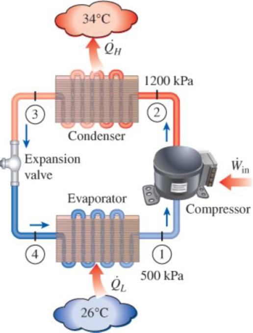
An air conditioner with refrigerant-134a as the working fluid is used to keep a room at 26°C by rejecting the waste heat to the outside air at 34°C. The room is gaining heat through the walls and the windows at a rate of 250 kJ/min while the heat generated by the computer, TV, and lights amounts to 900 W. An unknown amount of heat is also generated by the people in the room. The condenser and evaporator pressures are 1200 and 500 kPa, respectively. The refrigerant is saturated liquid at the condenser exit and saturated vapor at the compressor inlet. If the refrigerant enters the compressor at a rate of 100 L/min and the isentropic efficiency of the compressor is 75 percent, determine (a) the temperature of the refrigerant at the compressor exit, (b) the rate of heat generation by the people in the room, (c) the COP of the air conditioner, and (d) the minimum volume flow rate of the refrigerant at the compressor inlet for the same compressor inlet and exit conditions.
FIGURE P11–115
(a)
The temperature of the refrigerant at the compressor exit.
Answer to Problem 115RP
The temperature of the refrigerant at the compressor exit is
Explanation of Solution
Show the T-s diagram as in Figure (1).
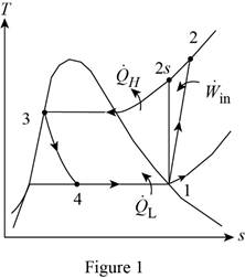
From Figure (1), write the specific enthalpy at state 3 is equal to state 4 due to throttling process.
Here, specific enthalpy at state 3 and 4 is
Express the specific enthalpy at state 2.
Here, specific enthalpy at state 2s is
Conclusion:
Perform the unit conversion of pressure at state 1 from
Refer Table A-13, “superheated refrigerant-134a”, and write the properties corresponding to pressure of
Here, specific enthalpy, volume and entropy is
Perform the unit conversion of pressure at state 2 from
Refer Table A-12, “saturated refrigerant-134a-pressure table”, and write the specific enthalpy at state 3 corresponding to pressure at state 3 of
Here, specific enthalpy at saturated liquid is
Substitute
Refer Table A-13, “superheated refrigerant 134a”, and write the specific enthalpy at state 2s corresponding to pressure at state 2 of
Write the formula of interpolation method of two variables.
Here, the variables denote by x and y is specific entropy at state 2 and specific enthalpy at state 2 respectively.
Show the specific enthalpy at state 2s corresponding to specific entropy as in Table (1).
|
Specific entropy at state 2 |
Specific enthalpy at state 2s |
| 0.9132 | 273.92 |
| 0.9242 | |
| 0.9268 | 278.28 |
Substitute
Thus, the specific enthalpy at state 2s is,
Substitute
Refer Table A-13, “superheated refrigerant 134a”, and write the temperature at state 2 corresponding to pressure at state 2 of
Show the temperature at state 2 corresponding to specific enthalpy at state 2 as in Table (2).
|
Specific enthalpy at state 2s |
Temperature at state 2 |
| 278.28 | 50 |
| 283.48 | |
| 289.66 | 60 |
Use excels and tabulates the values form Table (2) in Equation (III) to get,
Hence, the temperature of the refrigerant at the compressor exit is
(b)
The rate of heat generation by the people in the room.
Answer to Problem 115RP
The rate of heat generation by the people in the room is
Explanation of Solution
Express the mass flow rate of the refrigerant.
Here, volume flow rate at state 1 is
Express the refrigeration load.
Express the rate of heat generation by the people in the room.
Here, rate of heat generated is
Conclusion:
Substitute
Substitute
Substitute
Hence, the rate of heat generation by the people in the room is
(c)
The COP of the air conditioner.
Answer to Problem 115RP
The COP of the air conditioner is
Explanation of Solution
Express the rate of work input.
Express the coefficient of performance of the air conditioner.
Conclusion:
Substitute
Substitute
Hence, the COP of the air conditioner is
(d)
The minimum volume flow rate of the refrigerant at the compressor inlet.
Answer to Problem 115RP
The minimum volume flow rate of the refrigerant at the compressor inlet is
Explanation of Solution
Express the reversible coefficient of performance of the cycle.
Here, high and low temperature medium is
Express corresponding minimum power input.
Express the minimum mass flow rate.
Express the minimum volume flow rate of the refrigerant at the compressor inlet
Conclusion:
Substitute
Substitute
Substitute
Substitute
Hence, the minimum volume flow rate of the refrigerant at the compressor inlet is
Want to see more full solutions like this?
Chapter 11 Solutions
Thermodynamics: An Engineering Approach


- NOTE: This is a multi-part question. Once an answer is submitted, you will be unable to return to this part. A commercial refrigerator with refrigerant-134a as the working fluid is used to keep the refrigerated space at -30°C by rejecting its waste heat to cooling water that enters the condenser at 18°C at a rate of 0.28 kg/s and leaves at 26°C. The refrigerant enters the condenser at 1.2 MPa and 65°C and leaves at 42°C. The inlet state of the compressor is 60 kPa and -34°C and the compressor is estimated to gain a net heat of 420 W from the surroundings. The heat exchanger loses no heat to the environment. 26°C 42°C I Condenser Expansion valve Evaporator QL Water 18°C 1.2 MPa 65°C Qin Win Compressor 60 kPa -34°C Determine the COP of the refrigerator. (You must provide an answer before moving on to the next part.) The COP of the refrigerator isarrow_forwardNOTE: This is a multi-part question. Once an answer is submitted, you will be unable to return to this part. A commercial refrigerator with refrigerant-134a as the working fluid is used to keep the refrigerated space at -30°C by rejecting its waste heat to cooling water that enters the condenser at 18°C at a rate of 0.28 kg/s and leaves at 26°C. The refrigerant enters the condenser at 1.2 MPa and 65°C and leaves at 42°C. The inlet state of the compressor is 60 kPa and -34°C and the compressor is estimated to gain a net heat of 420 W from the surroundings. The heat exchanger loses no heat to the environment. 26°C 42°C Expansion valve 4 Condenser ↓ Evaporator Water 18°C QL 1.2 MPa 65°C Qin W in Compressor 60 kPa -34°C Determine the quality of the refrigerant at the evaporator inlet. (Take the required values from saturated refrigerant-134a tables.) (You must provide an answer before moving on to the next part.) The quality of the refrigerant at the evaporator inlet isarrow_forwardNOTE: This is a multi-part question. Once an answer is submitted, you will be unable to return to this part. A commercial refrigerator with refrigerant-134a as the working fluid is used to keep the refrigerated space at -30°C by rejecting its waste heat to cooling water that enters the condenser at 18°C at a rate of 0.29 kg/s and leaves at 26°C. The refrigerant enters the condenser at 1.2 MPa and 65°C and leaves at 42°C. The inlet state of the compressor is 60 kPa and -34°C and the compressor is estimated to gain a net heat of 430 W from the surroundings. The heat exchanger loses no heat to the environment. Water 26°C 18°C 1.2 MPa 42°C 65°C (2 t ein (3 Condenser Expansion valve in Evaporator Compressor 60 kPa -34°C 4 Determine the quality of the refrigerant at the evaporator inlet. (Take the required values from saturated refrigerant-134a tables.) (You must provide an answer before moving on to the next part.) The quality of the refrigerant at the evaporator inlet isarrow_forward
- A real heat pump has .02 kg/s of refrigerant R-134a flowing through it and it consumes 3kW of power. The refrigerant is a mixture at 50% quality and 120 kPa entering the evaporator and leaves at 100 kPa and -20 C. The refrigerant enters the condenser at 1.4 MPa and leaves at 1.2 MPa . Assuming no loss in pressure or temperature in the connecting pipes, determine the Temperature, Pressure, Enthalpy and Entropy at all positions in the cycle, the heat transfer coming in and leaving , the COP of this heat pump, the Isentropic Efficiency of the compressor and the rate of Entropy Generation in the compressor and of the Throttling process. This is a Thermodynamics question The refrigerant in this problem is R-134aarrow_forwardFill in the blanks: A refrigeration system operates on an ideal vapor compression using R-134a with an evaporator temperature of -30°C and a condenser exit temperature of 46°C and requires a 74.6 kW motor to drive the compressor. What is the capacity of the refrigerator in TOR? Use the properties of R-134a from refrigerants' table. ToRarrow_forwardA real Heat Pump has .02 kg/s of refrigerant flowing through it and consumes 3 kW of power. The refrigerant is a mixture at 50% quality and 120 kPa entering the evaporator and leaves at 100 kPa and -20 C The refrigerant enters the condenser at 1.4 MPa and leaves at 1.2 MPa Assuming no loss in pressure or temperature in the connecting pipes determine the Temperature, Pressure, Enthalpy and Entropy at all positions in the cycle, the heat transfer coming in and leaving, the COP of this Heat Pump, the Isentropic Efficiency of the compressor and the rate of entropy generation in the compressor and of the throttling processarrow_forward
- Refrigerant 22 is the working fluid in a Carnot vapor refrigeration cycle for which the evaporator temperature is -30°C. Saturated vapor enters the condenser at 36°C, and saturated liquid exits at the same temperature. The mass flow rate of refrigerant is 10 kg/min. Determine the rate of heat transfer to the refrigerant passing through the evaporator, in kW,arrow_forwardA cold storage is to be maintained at – 5°C while the surroundings are at 35°C. The heat leakage from the surroundings into the cold storage is estimated to be 28 kW. The actual C.O.P. of the refrigeration plant used is one fourth that of an ideal plant working between the same temperatures. Find the power required to drive the plant. show t-s diagramarrow_forwardTwo evaporator compression refrigeration system as shown in the pricutre below uses refrigerant134a as a working fluid. Evaporator 1 operates at 0 ºC, evaporator 2 operates at -26.4ºC, and thecondenser operates at 800 kPa. The refrigerant is circulated through the compressor at a rate of 0.5kg/s and the low-temperature evaporator serves a cooling load of 10 kW. The refrigerant is saturated liquid at the exit of the condenser and saturated vapor at the exit of each evaporator, and the compressor is isentropic efficiency is 95%. Determine a) the cooling rate of the high-temperature evaporator,b) the power required by the compressor, c) the COP of the cycle.arrow_forward
- A refrigerant system with a capacity of 15 tons of refrigeration operates at 150 KPA evaporator while in the condenser is 1380 KPA if the refrigerant R-717 is in a saturated state calculate the theoretical power required to operate the compressor.arrow_forwardA refrigerating system has a load of 50 kJ/s uses ammonia as working fluid. The refrigerated space is kept at a temperature of –30°C. Condensing pressure is at 1.0 MPa. The ammonia refrigerant exits the evaporator with 5-degree superheat and at 160 kPa. Superheated refrigerant is discharged from the compressor at a temperature of 140°C. Wire drawing at the compressor suction is 5 kPa and the compressor discharge is 20 kPa. If the overall mechanical efficiency is 82%, determine the power input to the compressor.arrow_forwardA real heat pump has .02 kg/s of refrigerant-134a flowing through and consumes 3 kW of power. The refrigerant is a mixture at 50% quality and 120 kPa entering the evaporator and leaves at 100 kPa and -20 C. The refrigerant enters the condenser at 1.4 MPa and leaves at 1.2 MPa. Assuming no loss in pressure or temperature in the connecting pipes, determine the temperature, pressure, enthalpy and entropy at all positions in the cycle, the heat transfer coming in and leaving, the COP of this heat pump, the isentropic efficiency of the compressor, and the rate of entropy generation in the compressor.arrow_forward
 Refrigeration and Air Conditioning Technology (Mi...Mechanical EngineeringISBN:9781305578296Author:John Tomczyk, Eugene Silberstein, Bill Whitman, Bill JohnsonPublisher:Cengage Learning