
Vector Mechanics for Engineers: Statics and Dynamics
12th Edition
ISBN: 9781259638091
Author: Ferdinand P. Beer, E. Russell Johnston Jr., David Mazurek, Phillip J. Cornwell, Brian Self
Publisher: McGraw-Hill Education
expand_more
expand_more
format_list_bulleted
Videos
Textbook Question
Chapter 10.1, Problem 10.42P
The position of boom ABC is controlled by the hydraulic cylinder BD. For the loading shown, determine the largest allowable value of the angle θ if the maximum force that the cylinder can exert on pin B is 25 kips.
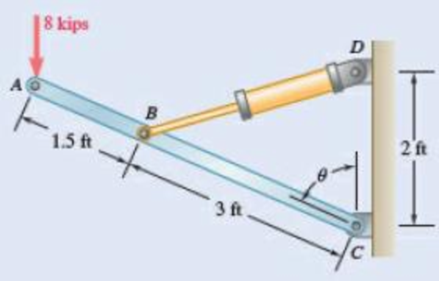
Fig. P10.41 and P10.42
Expert Solution & Answer
Want to see the full answer?
Check out a sample textbook solution
Students have asked these similar questions
4.2 in.
8.4 in.
4.2 in
8.4 in.
K J.
D
5 in.
120 lb
2.7 in.
- 12.6 in. 16.2 in.
Fig. P7.11 and P7.12
7.12 Two members each consisting of straight and 8.4-in.-radius
quarter-circle portions are connected as shown and support a 120-lb load at
D. Determine the internal forces at point K
For the steel truss and loading shown, determine the magnitude of the force (lb) of member BD, knowing that x = 14.1 ft, y = 7.6 ft, and P = 22538 lb. Round off only on the final answer expressed in 3 decimal places .
Solve Prob. 6.97 assuming that the 75-kN load has been removed.(Reference to Problem 6.97):The cab and motor units of the front-end loader shown are connected by a vertical pin located 2 m behind the cab wheels. The distance from C to D is 1 m. The center of gravity of the 300-kN motor unit is located at Gm , while the centers of gravity of the 100-kN cab and 75-kN load are located, respectively, at Gc and GI. . Knowing that the machine is at rest with its brakes released, determine (a) the reactions at each of the four wheels, (b) the forces exerted on the motor unit at C and D.
Chapter 10 Solutions
Vector Mechanics for Engineers: Statics and Dynamics
Ch. 10.1 - Determine the vertical force P that must be...Ch. 10.1 - Determine the horizontal force P that must be...Ch. 10.1 - Prob. 10.3PCh. 10.1 - Prob. 10.4PCh. 10.1 - Prob. 10.5PCh. 10.1 - A spring of constant 15 kN/m connects points C and...Ch. 10.1 - The two-bar linkage shown is supported by a pin...Ch. 10.1 - Determine the weight W that balances the 10-lb...Ch. 10.1 - Prob. 10.9PCh. 10.1 - Prob. 10.10P
Ch. 10.1 - Solve Prob. 10.10, assuming that the force P...Ch. 10.1 - Prob. 10.12PCh. 10.1 - Prob. 10.13PCh. 10.1 - Prob. 10.14PCh. 10.1 - Prob. 10.15PCh. 10.1 - 10.15 and 10.16 Derive an expression for the...Ch. 10.1 - Prob. 10.17PCh. 10.1 - Prob. 10.18PCh. 10.1 - Prob. 10.19PCh. 10.1 - Prob. 10.20PCh. 10.1 - Prob. 10.21PCh. 10.1 - A couple M with a magnitude of 100 Nm isapplied as...Ch. 10.1 - Rod AB is attached to a block at A that can...Ch. 10.1 - Solve Prob. 10.23, assuming that the 800-N force...Ch. 10.1 - In Prob. 10.9, knowing that a = 42 in., b = 28...Ch. 10.1 - Determine the value of corresponding to...Ch. 10.1 - Prob. 10.27PCh. 10.1 - Determine the value of corresponding to...Ch. 10.1 - Prob. 10.29PCh. 10.1 - Two rods AC and CE are connected by a pin at Cand...Ch. 10.1 - Solve Prob. 10.30 assuming that force P is movedto...Ch. 10.1 - Prob. 10.32PCh. 10.1 - Prob. 10.33PCh. 10.1 - Prob. 10.34PCh. 10.1 - Prob. 10.35PCh. 10.1 - Prob. 10.36PCh. 10.1 - Prob. 10.37PCh. 10.1 - Prob. 10.38PCh. 10.1 - Prob. 10.39PCh. 10.1 - Prob. 10.40PCh. 10.1 - Prob. 10.41PCh. 10.1 - The position of boom ABC is controlled by...Ch. 10.1 - Prob. 10.43PCh. 10.1 - Prob. 10.44PCh. 10.1 - Prob. 10.45PCh. 10.1 - Prob. 10.46PCh. 10.1 - Denoting the coefficient of static friction...Ch. 10.1 - Prob. 10.48PCh. 10.1 - Prob. 10.49PCh. 10.1 - Prob. 10.50PCh. 10.1 - Prob. 10.51PCh. 10.1 - Prob. 10.52PCh. 10.1 - Prob. 10.53PCh. 10.1 - Prob. 10.54PCh. 10.1 - Prob. 10.55PCh. 10.1 - Prob. 10.56PCh. 10.1 - Prob. 10.57PCh. 10.1 - Determine the horizontal movement of joint C if...Ch. 10.2 - Using the method of Sec. 10.2C, solve Prob. 10.29....Ch. 10.2 - Prob. 10.60PCh. 10.2 - Prob. 10.61PCh. 10.2 - Prob. 10.62PCh. 10.2 - Prob. 10.63PCh. 10.2 - Prob. 10.64PCh. 10.2 - Prob. 10.65PCh. 10.2 - Using the method of Sec. 10.2C, solve Prob. 10.38....Ch. 10.2 - Prob. 10.67PCh. 10.2 - Prob. 10.68PCh. 10.2 - Prob. 10.69PCh. 10.2 - Prob. 10.70PCh. 10.2 - Prob. 10.71PCh. 10.2 - Prob. 10.72PCh. 10.2 - Prob. 10.73PCh. 10.2 - Prob. 10.74PCh. 10.2 - A load W of magnitude 144 lb is applied to...Ch. 10.2 - Solve Prob. 10.75, assuming that the spring...Ch. 10.2 - Bar ABC is attached to collars A and B that...Ch. 10.2 - Solve Prob. 10.77, assuming that the spring...Ch. 10.2 - Prob. 10.79PCh. 10.2 - Prob. 10.80PCh. 10.2 - Prob. 10.81PCh. 10.2 - A spring AB of constant k is attached to two...Ch. 10.2 - Prob. 10.83PCh. 10.2 - Prob. 10.84PCh. 10.2 - Prob. 10.85PCh. 10.2 - Prob. 10.86PCh. 10.2 - Prob. 10.87PCh. 10.2 - Prob. 10.88PCh. 10.2 - Prob. 10.89PCh. 10.2 - Prob. 10.90PCh. 10.2 - Prob. 10.91PCh. 10.2 - Prob. 10.92PCh. 10.2 - Prob. 10.93PCh. 10.2 - Prob. 10.94PCh. 10.2 - Prob. 10.95PCh. 10.2 - Prob. 10.96PCh. 10.2 - Bars AB and BC, each with a length l and of...Ch. 10.2 - Solve Prob. 10.97 knowing that l = 30 in. and k =...Ch. 10.2 - Bars AB and CD, each of length l and of negligible...Ch. 10.2 - Solve Prob. 10.99, assuming that the vertical...Ch. 10 - Determine the vertical force P that must be...Ch. 10 - Determine the couple M that must be applied...Ch. 10 - Prob. 10.103RPCh. 10 - Prob. 10.104RPCh. 10 - Prob. 10.105RPCh. 10 - Prob. 10.106RPCh. 10 - Prob. 10.107RPCh. 10 - Prob. 10.108RPCh. 10 - Prob. 10.109RPCh. 10 - Prob. 10.110RPCh. 10 - Prob. 10.111RPCh. 10 - Prob. 10.112RP
Knowledge Booster


Learn more about
Need a deep-dive on the concept behind this application? Look no further. Learn more about this topic, mechanical-engineering and related others by exploring similar questions and additional content below.Similar questions
- Q.1) Draw Free-Body diagrams of each of the three cylinders shown below. Each of the cylinders has a diameter of 12 inches and weight of 300 lb. Determine the forces exerted on each cylinder. B E 40° 40° C Farrow_forwardQ.1) Draw Free-Body diagrams of each of the three cylinders shown below. Each of the cylinders has a diameter of 15 inches and weight of 400 lb. Determine the forces exerted on each cylinder. A 40° B 40° D C G E Farrow_forward! Required information The hydraulic cylinder CF, which partially controls the position of rod DE, has been locked in the position shown. Member BD is 15 mm thick and is connected at C to the vertical rod by a 9-mm-diameter bolt. Know that P= 2.8 kN and 0 = 75°. 100 mm 175 mm Vo B 20 200 mm F 45 mm Determine the bearing stress at Cin member BD. The bearing stress at Cin member BD is 63.544 MPa.arrow_forward
- Solve Prob. 10.32 assuming that the 900-N vertical force is applied at C instead of E.Reference to Problem 10.32:Two bars AD and DG are connected by a pin at D and by a spring AG . Knowing that the spring is 300 mm long when unstretched and that the constant of the spring is 5 kN/m, determine the value of x corresponding to equilibrium when a 900-N load is applied at E as shown.arrow_forward-2 m -2 m – 4.5 kN 1.4 kN E 2.8 kN Do G 0.5 m F 1 kN I kN B 3 m I kN. I kN A |C I 1 m '1m 1 m 1 m Fig. P6.15 and P6.16 6.16 For the Gambrel roof truss shown, determine the force in members CG and CI and in each of the members located to the right of the centerline of the truss. State whether each member is in tension or compression.arrow_forwardProblem 10: The 48-kg collar G is released from rest in the position shown and is stopped by plate BDF that is attached to the 20-mm-diameter steel rod CD and to the 15-mm-diameter steel rods AB and EF. Knowing that for the grade of steel used allowable normal stress of 180 MPa and E=200 GPa, determine the largest allowable distance h. ACE 2.5m С D B Farrow_forward
- PROBLEM 10.21 10.21 The uniform brass bar AB has a rectangular cross section and is supported by pins and brackets as shown. Each end of the bar can rotate freely about a horizontal axis through the pin, but rotation about a vertical axis is prevented by the brackets. (a) Determine the ratio bld for which the factor of safety is the same about the horizontal and vertical axes. (b) Determine the factor of safety if P = 8 L = 2m, d = 38 mm, and E = 105 GPa. B kN,arrow_forwardReferring to Prob. 10.43 and using the value found for the force exerted by the hydraulic cylinder CD , determine the change in the length of CD required to raise the 10-kN load by 15 mm.Reference to Problem 10.43:arrow_forwardA container of weight W is suspended from ring A. Cable BAC passes through the ring and is attached to fixed supports at B and C. Two forces P = Pi and Q = Qk are applied to the ring to maintain the container in the position shown. Knowing that W = 542 N, determine P and Q. (Hint: The tension is the same in both portions of cable BAC.) 150 mm 140 mm B 240 mm 130 mm 420 mm P Warrow_forward
- For the steel truss and loading shown, determine the magnitude of the force (lb) of member BE, knowing that x = 12.2 ft, y = 7.8 ft, and P = 28550 lb. Round off only on the final answer expressed in 3 decimal places .arrow_forwardFor the steel truss and loading shown, determine the magnitude of the force (lb) of member CE, knowing that x = 14.2 ft, y = 7.3ft, and P = 29917 lb. Round off only on the final answer expressed in 3 decimal places .arrow_forwardA mechanic is reinstalling a newly-sharpened blade on a lawn mower. A wedged-in block of wood at C prevents the blade from rotating as the 29-lb force is applied to the wrench handle. The blade is bolted to a bracket attached to the motor shaft O, which protrudes through the bracket and blade. Determine the normal force at C. State any assumptions. Does it matter whether the bolt at B is installed? 6.5" 2.02.0" 5.9" 29 lb Answer: Nc = i Ibarrow_forward
arrow_back_ios
SEE MORE QUESTIONS
arrow_forward_ios
Recommended textbooks for you
 Elements Of ElectromagneticsMechanical EngineeringISBN:9780190698614Author:Sadiku, Matthew N. O.Publisher:Oxford University Press
 Mechanics of Materials (10th Edition)Mechanical EngineeringISBN:9780134319650Author:Russell C. HibbelerPublisher:PEARSON
 Thermodynamics: An Engineering ApproachMechanical EngineeringISBN:9781259822674Author:Yunus A. Cengel Dr., Michael A. BolesPublisher:McGraw-Hill Education
 Control Systems EngineeringMechanical EngineeringISBN:9781118170519Author:Norman S. NisePublisher:WILEY
 Mechanics of Materials (MindTap Course List)Mechanical EngineeringISBN:9781337093347Author:Barry J. Goodno, James M. GerePublisher:Cengage Learning
 Engineering Mechanics: StaticsMechanical EngineeringISBN:9781118807330Author:James L. Meriam, L. G. Kraige, J. N. BoltonPublisher:WILEY
Elements Of Electromagnetics
Mechanical Engineering
ISBN:9780190698614
Author:Sadiku, Matthew N. O.
Publisher:Oxford University Press
Mechanics of Materials (10th Edition)
Mechanical Engineering
ISBN:9780134319650
Author:Russell C. Hibbeler
Publisher:PEARSON
Thermodynamics: An Engineering Approach
Mechanical Engineering
ISBN:9781259822674
Author:Yunus A. Cengel Dr., Michael A. Boles
Publisher:McGraw-Hill Education
Control Systems Engineering
Mechanical Engineering
ISBN:9781118170519
Author:Norman S. Nise
Publisher:WILEY
Mechanics of Materials (MindTap Course List)
Mechanical Engineering
ISBN:9781337093347
Author:Barry J. Goodno, James M. Gere
Publisher:Cengage Learning
Engineering Mechanics: Statics
Mechanical Engineering
ISBN:9781118807330
Author:James L. Meriam, L. G. Kraige, J. N. Bolton
Publisher:WILEY
How to balance a see saw using moments example problem; Author: Engineer4Free;https://www.youtube.com/watch?v=d7tX37j-iHU;License: Standard Youtube License