
Mechanics of Materials (MindTap Course List)
9th Edition
ISBN: 9781337093347
Author: Barry J. Goodno, James M. Gere
Publisher: Cengage Learning
expand_more
expand_more
format_list_bulleted
Videos
Textbook Question
Chapter 9, Problem 9.10.1P
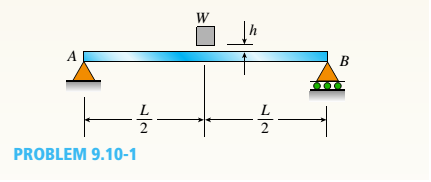
A heavy object of weight W is dropped onto the midpoint of a simple beam AB from a height h (see figure).
Obtain a formula for the maximum bending stress ^ma* due to tne filing weight in terms of h,
5st, where
Plot a graph of the ratio o"max/ö"it (that is, the ratio of the dynamic stress to the static stress) versus the ratio iifS^r(Let h/S^ vary from 0 to 10.)
Expert Solution & Answer
Want to see the full answer?
Check out a sample textbook solution
Chapter 9 Solutions
Mechanics of Materials (MindTap Course List)
Ch. 9 - The equation of the deflection curve for a...Ch. 9 - The equation of the deflection curve for a simply...Ch. 9 - -3 The deflection curve for a simple beam AB (see...Ch. 9 - The deflection curve for a simple beam AB (sec...Ch. 9 - The deflection curve for a cantilever beam AB (sec...Ch. 9 - The deflection curve for a cantilever beam AB (see...Ch. 9 - A simply supported beam is loaded with a point...Ch. 9 - A I-meter-long, simply supported copper beam (E =...Ch. 9 - A wide-flange beam (W 12 x 35) supports a uniform...Ch. 9 - A uniformly loaded, steel wide-flange beam with...
Ch. 9 - What is the span length L of a uniformly loaded,...Ch. 9 - -6 Calculate the maximum deflection of a uniformly...Ch. 9 - A cantilever beam with a uniform load (see figure)...Ch. 9 - A gold-alloy microbeam attached to a silicon wafer...Ch. 9 - Obtain a formula for the ratio c/maxof the...Ch. 9 - A cantilever beam model is often used to represent...Ch. 9 - B cams AB and CDE are connected using rigid link...Ch. 9 - -12 Derive the equation of the deflection curve...Ch. 9 - -13 Derive the equation of the deflection curve...Ch. 9 - -14 A cantilever beam AB supporting a triangularly...Ch. 9 - A cantilever beam has a length L = 12 ft and a...Ch. 9 - A simple beam with an overhang is subjected to d...Ch. 9 - -17 A cantilever beam AB is acted upon by a...Ch. 9 - -18 The beam shown in the figure has a sliding...Ch. 9 - -19 Derive the equations of the deflect ion curve...Ch. 9 - -20 Derive the equations of the deflection curve...Ch. 9 - -21 Derive the equations of the deflection curve...Ch. 9 - -22 Derive the equations of the deflection curve...Ch. 9 - -23 The beam shown in the figure has a sliding...Ch. 9 - -1 Derive the equation of the deflection curve for...Ch. 9 - -2 A simple beam AB is subjected to a distrib uted...Ch. 9 - -3 The simple beam AB shown in the figure has...Ch. 9 - -4 A beam with a uniform load has a sliding...Ch. 9 - -5 The distributed load acting on a cantilever...Ch. 9 - -6 A cantilever beam .4B is subjected to a...Ch. 9 - -7 A beam on simple supports is subjected to a...Ch. 9 - Derive the equation of the deflection curve for...Ch. 9 - -9 Derive the equations of the deflection curve...Ch. 9 - -10 Derive the equations of the deflection curve...Ch. 9 - A simply supported beam (E = 1600 ksi) is loaded...Ch. 9 - A simply supported beam (E = 12 GPa) carries a...Ch. 9 - Copper beam AB has circular cross section with a...Ch. 9 - Beam ABC is loaded by a uniform load q and point...Ch. 9 - A cantilever beam of a length L = 2.5 ft has a...Ch. 9 - A cantilever beam carries a trapezoidal...Ch. 9 - -5-7 A cantilever beam AB carries three equalaly...Ch. 9 - A simple beam AB supports five equally spaced...Ch. 9 - The cantilever beam AB shown in the figure has an...Ch. 9 - Beam ACE hangs from two springs, as shown in the...Ch. 9 - What must be the equation y =f(x) of the axis of...Ch. 9 - -12 Determine the angle of rotation Band...Ch. 9 - The cantilever beam ACE shown in the figure has...Ch. 9 - A cantilever beam is subjected to load P at...Ch. 9 - Use the method of superposition to find the angles...Ch. 9 - Repeat Problem 9,5-15 for the anti-symmetric...Ch. 9 - A cantilever beam is subjected to a quadratic...Ch. 9 - A beam ABCD consisting of a simple span BD and an...Ch. 9 - A horizontal load P acts at end C of the bracket...Ch. 9 - A beam ABC having flexural rigidity EI = 75 kN irT...Ch. 9 - Determine the angle of rotation 0Band deflectionCh. 9 - -22 A simple beam AB supports a uniform load of...Ch. 9 - The overhanging beam A BCD supports two...Ch. 9 - A thin metal strip of total weight W and length L...Ch. 9 - An overhanging beam ABC with flexural rigidity EI...Ch. 9 - A beam A BCD rests on simple supports at B and C...Ch. 9 - The compound beam ABC shown in the figure has a...Ch. 9 - A compound beam ABC DE (see figure) consists of...Ch. 9 - A steel beam ABC is simply supported at A and held...Ch. 9 - -30. Calculate the deflection at point C of a beam...Ch. 9 - Compound beam ABC is loaded by point load P = 1.5...Ch. 9 - The compound beam shown in the figure consists of...Ch. 9 - -33 Find the horizontal deflection hand verti cal...Ch. 9 - The fr a me A BCD shown in the heure is squeezed...Ch. 9 - A framework A BCD is acted on by counterclockwise...Ch. 9 - A framework A BCD is acted on by force P at 2L/3...Ch. 9 - A beam ABCDE has simple supports at B and D and...Ch. 9 - A frame ABC is loaded at point C by a force P...Ch. 9 - The wing of a large commercial jet is represented...Ch. 9 - The wing of a small plane is represented by a...Ch. 9 - Find an expression for required moment MA(in terms...Ch. 9 - Find an expression for required moment MA(in terms...Ch. 9 - Find required distance d (in terms of L) so that...Ch. 9 - A cantilever beam has two triangular loads as...Ch. 9 - -1 A cantilever beam AB is subjected to a uniform...Ch. 9 - The load on a cantilever beam AB has a triangular...Ch. 9 - A cantilever beam AB is subjected to a...Ch. 9 - Determine the angle of rotation BBand the...Ch. 9 - -5 Calen1ate the deflections S 3a ndCh. 9 - A cantileverbeam^Cßsupportstwo concentrated loads...Ch. 9 - Obtain formulas for the angle of rotation 0Aat...Ch. 9 - A simple beam AB supports two concentrated loads P...Ch. 9 - A simple beam AB is subjected to a load in the...Ch. 9 - -10 The simple beam AB shown in the figure...Ch. 9 - A simple beam AB is subjected to couples M0and 2A0...Ch. 9 - The cantilever beam ACB shown in the figure has...Ch. 9 - The cantilever beam ACB shown in the figure...Ch. 9 - Beam ACB hangs from two springs, as shown in the...Ch. 9 - -4 A simple beam ABCD has moment of inertia I near...Ch. 9 - A beam ABC has a rigid segment from A to B and a...Ch. 9 - A simple beam ABC has a moment of inertia 1,5 from...Ch. 9 - The tapered cantilever beam AB shown in the figure...Ch. 9 - The tapered cantilever beam AB shown in the figure...Ch. 9 - A tapered cantilever beam A B supports a...Ch. 9 - A tapered cantilever beam AB supports a...Ch. 9 - Repeat Problem 97-10, but now use the tapered...Ch. 9 - A simple beam ACE is constructed with square cross...Ch. 9 - A uniformly loaded simple beam AB (see figure) of...Ch. 9 - A simple beam AB of length L supports a...Ch. 9 - A propped cantilever beam AB of length L and with...Ch. 9 - A simple beam AB of length L is subjected to loads...Ch. 9 - A beam ABC with simple supports at A and B and an...Ch. 9 - A simple beam ACB supporting a uniform load q over...Ch. 9 - The frame shown in the figure consists of a beam...Ch. 9 - A simple beam AB of length L is loaded at the...Ch. 9 - The simple beam shown in the figure supports a...Ch. 9 - An overhanging beam ABC supports a concentrated...Ch. 9 - The cantilever beam shown in the figure supports a...Ch. 9 - A simple beam ACB supports a uniform load of...Ch. 9 - A cantilever beam ACB supports two concentrated...Ch. 9 - The cantilever beam A CB shown in the hgure is...Ch. 9 - The frame A BC support s a concentrated load P at...Ch. 9 - A simple beam ABC DE supports a uniform load of...Ch. 9 - An overhanging beam ABC is subjected to a couple...Ch. 9 - An overhanging beam ABC rests on a simple support...Ch. 9 - A symmetric beam A BCD with overhangs at both ends...Ch. 9 - A heavy object of weight W is dropped onto the...Ch. 9 - An object of weight Wis dropped onto the midpoint...Ch. 9 - A cantilever beam AB of length L = 6 It is...Ch. 9 - A weight W = 20 kN falls through a height h = 1,0...Ch. 9 - A weight W = 4000 lb falls through a height h =...Ch. 9 - An overhanging beam ABC with a rectangular cross...Ch. 9 - A heavy flywheel rotates at an angular speed m...Ch. 9 - A simple beam AB of length L and height /;...Ch. 9 - A cantilever beam JA of length Land height/; (see...Ch. 9 - An overhanging beam ABC of height h has a sliding...Ch. 9 - A simple beam AB of length L and height h (see...Ch. 9 - Beam AB has an elastic support kR at A, pin...
Knowledge Booster


Learn more about
Need a deep-dive on the concept behind this application? Look no further. Learn more about this topic, mechanical-engineering and related others by exploring similar questions and additional content below.Similar questions
- A simple beam of length L = 5 m carries a uniform load of intensity q = 5,8 kN/m and a concentrated load 22.5 kN (see figure). (a) Assuming tra]]ow = 110 MPa, calculate the required section modulus S. Then select the most economical wide-flange beam (W shape) from Table F-l(b) in Appendix F, and recalculate S, taking into account the weight of the beam. Select a new beam if necessary. (b) Repeat part (a), but now assume that the design requires that the W shape must be used in weak axis bending (i.e., it must bend about the 2-2 (or y) axis of the cross section).arrow_forwardCantilever beam AB carries an upward uniform load of intensity q1from x = 0 to L/2 (see Fig. a) and a downward uniform load of intensity q from x = L/2 to L. Find q1in terms of q if the resulting moment at A is zero. Draw V and M diagrams for the case of both q and qtas applied loadings. Repeat part (a) for the case of an upward triangularly distributed load with peak intensity q0(see Fig. b). For part (b), find q0, instead of q1arrow_forwardA counterclockwise moment M0acts at the midpoint of a fixed-end beam ACB of length L (see figure). Beginning with the second-order differential equation of the deflection curve (the bendingmoment equation), determine all reactions of the beam and obtain the equation of the deflection curve for the left-hand half of the beam. Then construct the shear-force and bending-moment diagrams for the entire beam, labeling all critical ordinales. Also, draw the deflection curve for the entire beam.arrow_forward
- A singly symmetric beam with a T-section (see figure) has cross-sectional dimensions b = 140 mm, a = 190, 8 mm, b. = 6,99 mm, and fc = 11,2 mm. Calculate the plastic modulus Z and the shape factor.arrow_forward(a) A simple beam AB with length L and height h supports a uniform load of intensity q (see the figure part a). Obtain a formula for the curvature shortening A of this beam. Also, obtain a formula for the maximum bending stress b in the beam due to the load q. Now assume that the ends of the beam are pinned so that curvature shortening is prevented and a horizontal force H develops at the supports (see the figure part b). Obtain a formula for the corresponding axial tensile stress t . Using the formulas obtained in parts (a) and (b), calculate the curvature shortening , the maximum bending stress b, and the tensile stress t for the following steel beam: length L = 3m, height h = 300 mm, modulus of elasticity E = 200 GPa, and moment of inertia I = 36 x 106 mm4. Also, the load on the beam has intensity q = 25 kN/m. Compare the tensile stress tproduced by the axial forces with the maximum bending stress bproduced by the uniform load.arrow_forwardA fixed-end beam AB of a length L supports a uniform load of intensity q (see figure). Beginning with the second-order differential equation of the deflection curve (the bending-moment equation), obtain the reactions, shear forces, bending moments, slopes, and deflections of the beam. Construct the shear-force and bending-moment diagrams, Labeling all critical ordinales.arrow_forward
- A beam with a channel section is subjected to a bending moment M having its vector at an angle 0 to the 2 axis (see figure). Determine the orientation of the neutral axis and calculate the maximum tensile stress et and maximum compressive stress ecin the beam. Use the following data: C 8 × 11.5 section, M = 20 kip-in., tan0=l/3. See Table F-3(a) of Appendix F for the dimensions and properties of the channel section.arrow_forwardFind expressions for shear force V and moment Mat x = 2L/3 of beam (a) in terms of peak load intensity q0 and beam length variable L. Repeat for beam (b).arrow_forwardA uniformly loaded, steel wide-flange beam with simple supports (see figure) has a downward deflection of 10 mm at the midpoint and angles of rotation equal to 0.01 radians at the ends. Calculate the height h of the beam if the maximum bending stress is 90 MPa and the modulus of elasticity is 200 GPa, (Use the formulas of Example 9-L)arrow_forward
- A simple beam AB is loaded as shown in the figure. Calculate the required section modulus S if ^aibw = IS,000 psi, L = 32 ft, P = 2900 lb, and g = 450 lb/ft. Then select a suitable I-beam (S shape) from Table F-2(a), Appendix F, and recalculate 5 taking into account the weight of the beam. Select a new beam size if necessary. What is the maximum load P that can be applied to your final beam selection in part (a)?arrow_forwardFind expressions for shear force V and moment M at mid-span of beam AB in terms of peak load intensity q0and beam length variables a and L Let a = 5L/b.arrow_forwardA r o lukI f/frm f «m t ub e of ou t sid e d ia met er ^ and a copper core of diameter dxare bonded to form a composite beam, as shown in the figure, (a) Derive formulas for the allowable bending moment M that can be carried by the beam based upon an allowable stress <7Ti in the titanium and an allowable stress (u in the copper (Assume that the moduli of elasticity for the titanium and copper are Er- and £Cu, respectively.) (b) If d1= 40 mm, d{= 36 mm, ETl= 120 GPa, ECu= 110 GPa, o-Ti = 840 MPa, and ctqj = 700 MPa, what is the maximum bending moment Ml (c) What new value of copper diameter dtwill result in a balanced design? (i.e., a balanced design is that in which titanium and copper reach allow- able stress values at the same time).arrow_forward
arrow_back_ios
SEE MORE QUESTIONS
arrow_forward_ios
Recommended textbooks for you
 Mechanics of Materials (MindTap Course List)Mechanical EngineeringISBN:9781337093347Author:Barry J. Goodno, James M. GerePublisher:Cengage Learning
Mechanics of Materials (MindTap Course List)
Mechanical Engineering
ISBN:9781337093347
Author:Barry J. Goodno, James M. Gere
Publisher:Cengage Learning
Mechanics of Materials Lecture: Beam Design; Author: UWMC Engineering;https://www.youtube.com/watch?v=-wVs5pvQPm4;License: Standard Youtube License