
Mechanics of Materials (MindTap Course List)
9th Edition
ISBN: 9781337093347
Author: Barry J. Goodno, James M. Gere
Publisher: Cengage Learning
expand_more
expand_more
format_list_bulleted
Videos
Textbook Question
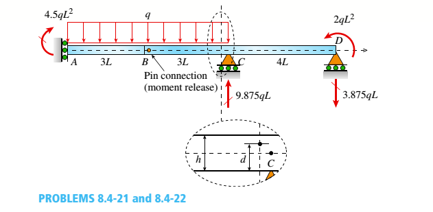
Chapter 8, Problem 8.4.22P
, Solve the preceding problem using the numerical data: /) = 90mm, h = 280 mm, d = 210 mm, q = 14 kN/m, and L = L2 m.
Expert Solution & Answer
Want to see the full answer?
Check out a sample textbook solution
Students have asked these similar questions
r2, E,
, E
L2
Two aluminum circular shafts (E=70GPA) are mounted according to the figure. The two shafts have the following dimensions: r1 = 6.9mm r2 = 11.1mm L1= 1.52m L2 = 1.29m. If the
load applied is P = 2.1 kN, what is the displacement at the point of application of P in mm (accuracy of 5%)?
A utility hook was formed from a round rod of diameter d= 0.75 in into the
geometry shown in the figure. Given: F= 1500 lbf, L = 7 in, and D;= 2.5 in.
NOTE: This is a multi-part question. Once an answer is submitted, you will be
unable to return to this part.
L.
Find Ixx of the plate shown below. where AB = 2 m, AC=12.5m, EF = 10m, FG = 2.5m, HD=3m.
A
B
(1)
E
F
(Enter only the values in the boxes by referring the unit given in bracket.)
C
The value of X (in m) =
The value of Y (in m) =
The value of lw1 (in m) =
The value of lw2 (in m4)
The value of Ix of the given plate (in m4) =
Chapter 8 Solutions
Mechanics of Materials (MindTap Course List)
Ch. 8 - A spherical balloon is filled with a gas. The...Ch. 8 - A spherical balloon with an outer diameter of 500...Ch. 8 - A large spherical tank (see figure) contains gas...Ch. 8 - Solve the preceding problem if the internal...Ch. 8 - A hemispherical window (or viewport) in a...Ch. 8 - A rubber ball (sec figure) is inflated to a...Ch. 8 - (a) Solve part (a) of the preceding problem if the...Ch. 8 - A spherical steel pressure vessel (diameter 500...Ch. 8 - A spherical tank of diameter 48 in. and wall...Ch. 8 - Solve the preceding problem for the following...
Ch. 8 - A spherical stainless-steel tank having a diameter...Ch. 8 - Solve the preceding problem if the diameter is 480...Ch. 8 - : A hollow, pressurized sphere having a radius r =...Ch. 8 - A fire extinguisher tank is designed for an...Ch. 8 - Prob. 8.3.2PCh. 8 - A scuba t a n k (see fig ure) i s bci ng d e...Ch. 8 - A tall standpipc with an open top (see figure) has...Ch. 8 - An inflatable structure used by a traveling circus...Ch. 8 - A thin-walled cylindrical pressure vessel of a...Ch. 8 - A strain gage is installed in the longitudinal...Ch. 8 - A circular cylindrical steel tank (see figure)...Ch. 8 - A cylinder filled with oil is under pressure from...Ch. 8 - Solve the preceding problem if F =90 mm, F = 42...Ch. 8 - A standpipe in a water-supply system (see figure)...Ch. 8 - A cylindrical tank with hemispherical heads is...Ch. 8 - : A cylindrical tank with diameter d = 18 in, is...Ch. 8 - A pressurized steel tank is constructed with a...Ch. 8 - Solve the preceding problem for a welded Tank with...Ch. 8 - A wood beam with a cross section 4 x 6 in. is...Ch. 8 - Prob. 8.4.2PCh. 8 - A simply supported beam is subjected to two point...Ch. 8 - A cantilever beam with a width h = 100 mm and...Ch. 8 - A beam with a width h = 6 in. and depth h = 8 in....Ch. 8 - Beam ABC with an overhang BC is subjected to a...Ch. 8 - A cantilever beam(Z, = 6 ft) with a rectangular...Ch. 8 - Solve the preceding problem for the following...Ch. 8 - A simple beam with a rectangular cross section...Ch. 8 - An overhanging beam ABC has a guided support at A,...Ch. 8 - Solve the preceding problem if the stress and...Ch. 8 - A cantilever wood beam with a width b = 100 mm and...Ch. 8 - . A cantilever beam (width b = 3 in. and depth h =...Ch. 8 - A beam with a wide-flange cross section (see...Ch. 8 - A beam with a wide-flange cross section (see...Ch. 8 - A W 200 x 41.7 wide-flange beam (see Table F-l(b),...Ch. 8 - A W 12 x 35 steel beam is fixed at A. The beam has...Ch. 8 - A W 360 x 79 steel beam is fixed at A. The beam...Ch. 8 - A W 12 X 14 wide-flange beam (see Table F-l(a),...Ch. 8 - A cantilever beam with a T-section is loaded by an...Ch. 8 - Beam A BCD has a sliding support at A, roller...Ch. 8 - , Solve the preceding problem using the numerical...Ch. 8 - A W 12 x 35 steel cantilever beam is subjected to...Ch. 8 - A W 310 x 52 steel beam is subjected to a point...Ch. 8 - A solid circular bar is fixed at point A. The bar...Ch. 8 - A cantilever beam with a width h = 100 mm and...Ch. 8 - Solve the preceding problem using the following...Ch. 8 - A cylindrical tank subjected to internal...Ch. 8 - A cylindrical pressure vessel having a radius r =...Ch. 8 - A pressurized cylindrical tank with flat ends is...Ch. 8 - A cylindrical pressure vessel with flat ends is...Ch. 8 - The tensional pendulum shown in the figure...Ch. 8 - The hollow drill pipe for an oil well (sec figure)...Ch. 8 - Solve the preceding problem if the diameter is 480...Ch. 8 - . A segment of a generator shaft with a hollow...Ch. 8 - A post having a hollow, circular cross section...Ch. 8 - A sign is supported by a pole of hollow circular...Ch. 8 - A sign is supported by a pipe (see figure) having...Ch. 8 - A traffic light and signal pole is subjected to...Ch. 8 - Repeat the preceding problem but now find the...Ch. 8 - A bracket ABCD having a hollow circular cross...Ch. 8 - A gondola on a ski lift is supported by two bent...Ch. 8 - Beam A BCD has a sliding support at A, roller...Ch. 8 - A double-decker bicycle rack made up of square...Ch. 8 - A semicircular bar AB lying in a horizontal plane...Ch. 8 - Repeat Problem 8.5-22 but replace the square tube...Ch. 8 - An L-shaped bracket lying in a horizontal plane...Ch. 8 - A horizontal bracket ABC consists of two...Ch. 8 - , An arm A BC lying in a horizontal plane and...Ch. 8 - A crank arm consists of a solid segment of length...Ch. 8 - A moveable steel stand supports an automobile...Ch. 8 - A mountain bike rider going uphill applies a force...Ch. 8 - Determine the maximum tensile, compressive, and...Ch. 8 - Prob. 8.5.32PCh. 8 - A plumber's valve wrench is used to replace valves...Ch. 8 - A compound beam ABCD has a cable with force P...Ch. 8 - A steel hanger bracket ABCD has a solid, circular...
Knowledge Booster


Learn more about
Need a deep-dive on the concept behind this application? Look no further. Learn more about this topic, mechanical-engineering and related others by exploring similar questions and additional content below.Similar questions
- Solve the preceding problem for the following data: diameter LO m, thickness 48 mm, pressure 22 MPa, modulus 210 GPa. and Poisson's ratio 0.29arrow_forward1: The forces as given below are applied as shown in the figure. Fi=10 kN, F2=5 kN and F3=3 kN. The diameter of the circular bar is 40 mm. Calculate the followings at point D; a) o and tp b) Principal stresses c) o, based on maximum principal stress theory d) o, based on maximum shear stress theory e) o, based on maximum deformation energy theory (Von Mises) F2 F3 F1 D 150 mm 350 mmarrow_forwardIn the figure below, A 50 mm shaft is subjected to a reversed load P = 2700 N. Find the length (L), if the stress at the fillet equal to the stress at the center. 6.25mm 2700N 2700N 62.5 s0 375 Fillet Center Fillet All Dimensions in mmarrow_forward
- L,=40mm; L,= 120mm; L=100mm and 0,=65°. Find the possible value of 0, and 0, L,=80mm and 3.arrow_forwardFind the stresses in each direction, also find the change in volume of the block of dimension 120 mm x 45 mm x 43 mm, subjected to 3 mutually perpendicular loads. The load along length, breadth and depth directions are 10 kN (tensile), 20 kN (compressive), 16 kN (compressive) respectively. Take E as 140 GPa, Poisson’s ratio as 0.3 The stress along length direction (Unit in MN/m2)= The compressive stress along width direction (Unit in MN/m2)= The compressive stress along depth direction (Unit in MN/m2)= The change in volume of the block is (unit in mm3) =arrow_forwardWrite the solution for the following: Member BC= 600 N Member FG = -600 Narrow_forward
- The dimensions are of the graph are d1 = 7 cm , L1 = 6 m , d2 = 4.2 cm , and L2 = 5 m with applied loads F1 = 130 kN and F2 = 60 kN . The modulus of elasticity is E = 80 GPa . Use the following steps to find the deflection at point D. Point B is halfway between points A and C. What is the reaction force at A? Let a positive reaction force be to the right.arrow_forward11:11 A The wood beam has an allowable shear stress of Tallow = 9.6 MPa. d3 d3 Variable d₁ d₂ d1 d3 d4 d5 wamap.org Value d2 V Values for the figure are given in the following table. Note the figure may not be to scale. 0.05 m 0.125 m 0.05 m 0.225 m P 0.1125 m d1 d5 a. Determine the Q at point P. b. Determine the moment of inertia, I. d4 c. Determine the magnitude of the max shear force that can be applied to the cross-section at point P, Vmax.arrow_forwardQ1: A circular steel rod ABCD is loaded as shown below. Use the following data to Find the maximum stress and the deformation (AL) of the rod. Take E = 200 GPa. A P1 L1 Dia. 1 L2 Dia. 2 C L3 P2 D D 30 mm o P3 Dia. 1 Dia. 2 P1 P2 P3 L1 L2 L3 Name (mm) (mm) (kN) (kN) (kN) (mm) (mm) (mm) 45 40 100 35 30 1300 2100 1300arrow_forward
- The recessed composite beam in the figure is made of steel and aluminum It was produced and a force of 20 kN was applied to its tip. According to what is given, the maximum amount of steel and aluminum Find the stresses. (Eç = 200 GPa, EAl = 80 GPa) dimensions in mmarrow_forward3) Solve the plane stress problem using two-element model to find displacements and stresses. 15 kN 30 mm E-70 GPa Thickness - 10 mmarrow_forwardThe horizontal member ABC supports a point load of P (KN) and is pin-supported at B and C. The member (link) DB is a structural steel that pin- supported at D with the given dimensions (All the pins will have 5mm diameter). a) If the force P=100 kN find the max shear stress in the pins. b) Find the max force P such that the member BD will remain elastic c) Find the max displacement of point A such #remain elasticarrow_forward
arrow_back_ios
SEE MORE QUESTIONS
arrow_forward_ios
Recommended textbooks for you
 Mechanics of Materials (MindTap Course List)Mechanical EngineeringISBN:9781337093347Author:Barry J. Goodno, James M. GerePublisher:Cengage Learning
Mechanics of Materials (MindTap Course List)
Mechanical Engineering
ISBN:9781337093347
Author:Barry J. Goodno, James M. Gere
Publisher:Cengage Learning
Understanding Failure Theories (Tresca, von Mises etc...); Author: The Efficient Engineer;https://www.youtube.com/watch?v=xkbQnBAOFEg;License: Standard youtube license