
Shigley's Mechanical Engineering Design (McGraw-Hill Series in Mechanical Engineering)
10th Edition
ISBN: 9780073398204
Author: Richard G Budynas, Keith J Nisbett
Publisher: McGraw-Hill Education
expand_more
expand_more
format_list_bulleted
Videos
Textbook Question
Chapter 8, Problem 76P
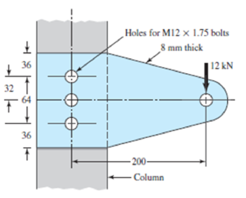
The cantilever bracket is bolted to a column with three M12 × 1.75 ISO 5.8 bolts. The bracket is made from AISI 1020 hot-rolled steel. Assume the bolt threads do not extend into the joint. Find the factors of safety for the following failure modes: shear of bolls, bearing of bolts, bearing of bracket, and bending of bracket.
Problem 8–76
Dimensions in millimeters.
Expert Solution & Answer
Want to see the full answer?
Check out a sample textbook solution
Students have asked these similar questions
The cantilever bracket Is bolted to a column with three M12 x 1.75 ISO 5.8 bolts. The bracket Is made from AISI 1020 hot-
rolled steel. Assume the bolt threads do not extend into the Joint. Find the factors of safety for the following fallure modes:
shear of bolts, bearing of bolts, bearing of bracket, and bending of the bracket. GIVE the overall jolnt factor of safety.
Given: F= 2 KN.
NOTE: This is a multi-part questlon. Once an answer Is submitted, you will be unable to return to this part.
Holes for M12 x 1.75 bolts
8 mm thick
36
32
36
- 200-
Column
Find the factor of safety with respect to the shear stress In the bolts.
The factor of safety with respect to the shear stress In the bolts ng Is
4.4
8-68
Engineering Design
+
40
1
plem 8-68
70
millimeters.
40
A bolted lap joint using ISO class 5.8 bolts and members made of cold-drawn SAE 1040 steel is
shown in the figure. Assume the bolt threads do not extend into the joint. Find the tensile shear load
F that can be applied to this connection to provide a minimum factor of safety of 2.5 for the fol-
lowing failure modes: shear of bolts, bearing on bolts, bearing on members, and tension of members.
20
M20x2.5
20
The figure shows a connection that employs three SAE grade 4 bolts. The tensile shear load on the joint is
4000 lbf. The members are bars of AISI 1020 HR steel. Assume the bolt threads do not extend into the joint.
Find the factor of safety for each possible mode of failure. (Refer example problem 8.6 on pg. 445).
in ∞
in 100
in
1 in
in
Đ
1in
-2 in
in-20 UNC
5
5
in
in
Chapter 8 Solutions
Shigley's Mechanical Engineering Design (McGraw-Hill Series in Mechanical Engineering)
Ch. 8 - A power screw is 25 mm in diameter and has a...Ch. 8 - Using the information in the footnote of Table...Ch. 8 - Show that for zero collar friction the efficiency...Ch. 8 - A single-threaded power screw is 25 mm in diameter...Ch. 8 - The machine shown in the figure can be used for a...Ch. 8 - The press shown for Prob. 8-5 has a rated load of...Ch. 8 - For the screw clamp shown, a force is applied at...Ch. 8 - The C clamp shown in the figure for Prob. 8-7 uses...Ch. 8 - Find the power required to drive a 1.5-in power...Ch. 8 - A single square-thread power screw has an input...
Ch. 8 - Prob. 11PCh. 8 - An M14 2 hex-head bolt with a nut is used to...Ch. 8 - Prob. 13PCh. 8 - A 2-in steel plate and a 1-in cast-iron plate are...Ch. 8 - Repeat Prob. 8-14 with the addition of one 12 N...Ch. 8 - A 2-in steel plate and a 1-in cast-iron plate are...Ch. 8 - Two identical aluminum plates are each 2 in thick,...Ch. 8 - Prob. 18PCh. 8 - A 30-mm thick AISI 1020 steel plate is sandwiched...Ch. 8 - Prob. 20PCh. 8 - Prob. 21PCh. 8 - Prob. 22PCh. 8 - A 2-in steel plate and a 1-in cast-iron plate are...Ch. 8 - An aluminum bracket with a 12-in thick flange is...Ch. 8 - An M14 2 hex-head bolt with a nut is used to...Ch. 8 - A 34 in-16 UNF series SAE grade 5 bolt has a 34-in...Ch. 8 - From your experience with Prob. 8-26, generalize...Ch. 8 - Prob. 28PCh. 8 - Prob. 29PCh. 8 - Prob. 30PCh. 8 - For a bolted assembly with eight bolts, the...Ch. 8 - Prob. 32PCh. 8 - 8-33 to 8-36 The figure illustrates the...Ch. 8 - 8-33 to 8-36 The figure illustrates the...Ch. 8 - 8-33 to 8-36 The figure illustrates the...Ch. 8 - 8-33 to 8-36 The figure illustrates the...Ch. 8 - Prob. 37PCh. 8 - Prob. 38PCh. 8 - 837 to 840 Repeat the requirements for the problem...Ch. 8 - Prob. 40PCh. 8 - 841 to 844 For the pressure vessel defined in the...Ch. 8 - Prob. 42PCh. 8 - Prob. 43PCh. 8 - Prob. 44PCh. 8 - Bolts distributed about a bolt circle are often...Ch. 8 - The figure shows a cast-iron bearing block that is...Ch. 8 - Prob. 47PCh. 8 - Prob. 48PCh. 8 - Prob. 49PCh. 8 - Prob. 50PCh. 8 - 851 to 854 For the pressure cylinder defined in...Ch. 8 - Prob. 52PCh. 8 - 851 to 854 For the pressure cylinder defined in...Ch. 8 - 851 to 854 For the pressure cylinder defined in...Ch. 8 - 855 to 858 For the pressure cylinder defined in...Ch. 8 - 855 to 858 For the pressure cylinder defined in...Ch. 8 - 855 to 858 For the pressure cylinder defined in...Ch. 8 - For the pressure cylinder defined in the problem...Ch. 8 - A 1-in-diameter hot-rolled AISI 1144 steel rod is...Ch. 8 - The section of the sealed joint shown in the...Ch. 8 - Prob. 61PCh. 8 - Prob. 62PCh. 8 - Prob. 63PCh. 8 - Prob. 64PCh. 8 - Using the Goodman fatigue criterion, repeat Prob....Ch. 8 - The figure shows a bolted lap joint that uses SAE...Ch. 8 - Prob. 67PCh. 8 - A bolted lap joint using ISO class 5.8 bolts and...Ch. 8 - Prob. 69PCh. 8 - The figure shows a connection that employs three...Ch. 8 - A beam is made up by bolting together two cold...Ch. 8 - Prob. 72PCh. 8 - Prob. 73PCh. 8 - Prob. 74PCh. 8 - A vertical channel 152 76 (see Table A7) has a...Ch. 8 - The cantilever bracket is bolted to a column with...Ch. 8 - Prob. 77PCh. 8 - The figure shows a welded fitting which has been...Ch. 8 - Prob. 79PCh. 8 - Prob. 80PCh. 8 - Prob. 81P
Knowledge Booster


Learn more about
Need a deep-dive on the concept behind this application? Look no further. Learn more about this topic, mechanical-engineering and related others by exploring similar questions and additional content below.Similar questions
- Calculate the maximum tensile stress developed in a 1/4-20 bolt (Major dia = 0.2500" and Root dia = 0.1959"), 3" long, and a head height of 0.1875", if it is subjected to a load of 426 lbs.arrow_forward1) The cantilever bracket is bolted to a column with three M12 x 1.75 ISO 5.8 bolts. The bracket is made from AISI 1020 hot-rolled steel. Holes for M12 X 1.75 bolts 8 mm thick Find the factors of safety for the following failure modes: shear of 36 | 12 kN bolts, bearing of bolts, bearing of bracket, and bending of bracket. 32 64 Solution: 36 200 Colummarrow_forwardThe shaft is shown in Figure 3 is modified using the shaft from Question 2. Manufacturer selected as machined surface treatment for the shaft. It contains two fillets and one groove. The shaft rotates at 3000 řpm, whilst the imposed loads remain static. (a) Ifthe shaft is subjected to two-point load as shown below, F =10 kN, Calculate the factor of safety with respect to fatigue failure. (b) If the shaft is subjected to two-point load F= 10 kN while transmitting a power of P = 32 kW, Calculate the factor of safety with respect to fatigue failure. (L1 = 70 mm, L2 = 100 mm, L3 = 80 mm, La = 40 mm, Ls = 50 mm, L6 = 30 mm, Rj = 2 mm, R2 1 mm, R3= 4 mm, d = 24mm and D = 32mm,) 0.3F 0.7F LI Ls L. L6 ノ R1 R3 R2arrow_forward
- Design a flanged coupling that will be able to carry power of 1,500 HP using a factor of safety of 3.3 at 630 rpm. The shaft diameters of the equipment the coupling will connect are both 5 inches. Check your design for the following stresses if N = 3.3 is satisfied: 1. Bolt shearing; 2. Bolt bearing; 3. Shearing of hub from coupling flange; 4. Shear on key; 5. Compression on key; Select dimensions whichever is higher. 6. Calculate also minimum length of engagement of the bolt and nut if these are of the same material. 5 inch dia. shafts coupling to connect the equipment shafts. Note: use 4 bolts only Instructions:arrow_forwardFor the lap connection shown, the rivets are 19-mm diameter and the plates are 8 mm thick. The rivets used are A502, Grade 1 and the plates are ASTM A36 with Fu = 400 MPa. Determine the value of Pin all possible modes of failure and the safe value of P that the connection can resist. Fv = 120 MPa, Fp = 1.2 Fu. Add 1.6 mm for the hole diameter. Ans. 297.6 KNarrow_forwardAs shown in figure below, two plates are clamped by washer-faced 2 in-20 UNF SAE grade 5 bolts each with a standard 2 N steel plain washer. The top plate is steel and the bottom pplate is gray cast iron. If a total of 8 bolts where used to close 1 feet diameter pipe which applied at maximum pressure of 150 psi. Calculate the static and fatigue safety factor of this joint. Used Goodman theory for tha fatigue safety 1/2 factor. 3/4arrow_forward
- The figure shows a section of a large coupling. Each bolt in this joint is subjected to cyclic load fluctuating between 0 and 13 kN. The members are made from steel. The members have equal thicknesses and total length of members is L=37 mm. Each bolt is initially tightened carefully to 78% of proof load. The bolt is to be Metric grade 5.8 M12x1.75 (coarse-pitch series). The threads has been manufactured by rolling and reliability for bolts is 95%. Calculate the stiffness of the bolt (in kN/mm). Yanıt:arrow_forwardProblem 5: At times in design, you would like to ensure that failure occurs in a specific part. For instance, in watch designs many components are stacked on top of one another due to the small space requirements. In this case if failure must occur, it is best that it happens in a gear that is easy to access. Using the maximum shear stress theory and only the stresses related to bending, determine the safety factors of the teeth on gears A, B, and C below. Each tooth can be assumed to be a rectangular cantilever beam with a point force at the end, the force can be determined using Torque = F x r. 0000 Gear B Gear C Gear A Torque on Shaft Gear Radius Tooth Length Tooth Height Tooth Thickness Gear A 10 N-mm 8.0 mm 1.5 mm 1.5 mm 0.5 mm Gear B 8 N-mm 3.0 mm 2.0 mm 1.5 mm 0.5 mm Gear C 6 N-mm 5.0 mm 1.5 mm 2.0 mm 0.8 mm Gear D Gear D 30 N-mm 10.0 mm 1.5 mm 1.5 mm Solve Material: Steel E =200 GPa Sy = 250 MPaarrow_forwardRequired information The bolted connection shown in the figure is subjected to a tensile shear load of 90 kN. The bolts are ISO class 5.8, and the material is cold-drawn AISI 1015 steel. Assume the bolt threads do not extend into the joint. Find the factor of safety of the connection for all possible modes of failure. Give the overall joint factor of safety. Given: t = 15 mm and t2 = 25 mm. NOTE: This is a multi-part question. Once an answer is submitted, you will be unable to return to this part. 35 60 60 - 35 t1 M20 x 2.5 35 35 + t2 Find the overall joint factor of safety. The overall joint factor of safety noverall isarrow_forward
- Calculate the dimensions of the I-section of a connecting rod, stating any assumptions. using the data below: Maximum cylinder pressure = 3.15N/mm² Cylinder bore = 100mm Factor of Safety=6 Crank length 95mm Connecting rod length=380mm Take the constant a=7500.arrow_forwardA rotating shaft of 40×4 mm AISI 1018 cold-drawn steel tubing has a 6 mm diameter hole drilled transversely through it. Estimate the factor of safety guarding against fatigue and static failures using the Gerber and Langer failure criteria for the following loading conditions: a. The shaft is subjected to a completely reversed torque of 120 N.m in phase with a completely reversed bending moment of 150 N.m. b. The shaft is subjected to a pulsating torque fluctuating from 20 to 160 N.m and as steady bending moment of 150 N.m.arrow_forwardCondition #1: A structural support for a machine is subjected to a static compression load of 20 kN. The support is manufactured from a circular rod made from SAE 1040 Hot Rolled steel. Specify suitable diameter for the cross section of the rod based on the basic size. Steel data are available in Table A-10 from the textbook. Condition #2: The same structural support of the basic size determined in Condition 1 is subjected to a tensile load of 15 kN that is repeated several thousand times over the life of the machine. This load is not an addition to the 20 kN. Specify a suitable steel that is suitable to this application based on the basic size determined in Condition #1. Loading of Condition #1 does not apply here. Condition #3: The same structural support from Condition 2 is heated from room temperature of 25°C. The support is placed inside a frame on both ends. There is a total clearance of 0.2 mm between the support and its frame. Initial length of the rod is 200 mm. Specify the…arrow_forward
arrow_back_ios
SEE MORE QUESTIONS
arrow_forward_ios
Recommended textbooks for you
 Elements Of ElectromagneticsMechanical EngineeringISBN:9780190698614Author:Sadiku, Matthew N. O.Publisher:Oxford University Press
 Mechanics of Materials (10th Edition)Mechanical EngineeringISBN:9780134319650Author:Russell C. HibbelerPublisher:PEARSON
 Thermodynamics: An Engineering ApproachMechanical EngineeringISBN:9781259822674Author:Yunus A. Cengel Dr., Michael A. BolesPublisher:McGraw-Hill Education
 Control Systems EngineeringMechanical EngineeringISBN:9781118170519Author:Norman S. NisePublisher:WILEY
 Mechanics of Materials (MindTap Course List)Mechanical EngineeringISBN:9781337093347Author:Barry J. Goodno, James M. GerePublisher:Cengage Learning
 Engineering Mechanics: StaticsMechanical EngineeringISBN:9781118807330Author:James L. Meriam, L. G. Kraige, J. N. BoltonPublisher:WILEY
Elements Of Electromagnetics
Mechanical Engineering
ISBN:9780190698614
Author:Sadiku, Matthew N. O.
Publisher:Oxford University Press
Mechanics of Materials (10th Edition)
Mechanical Engineering
ISBN:9780134319650
Author:Russell C. Hibbeler
Publisher:PEARSON
Thermodynamics: An Engineering Approach
Mechanical Engineering
ISBN:9781259822674
Author:Yunus A. Cengel Dr., Michael A. Boles
Publisher:McGraw-Hill Education
Control Systems Engineering
Mechanical Engineering
ISBN:9781118170519
Author:Norman S. Nise
Publisher:WILEY
Mechanics of Materials (MindTap Course List)
Mechanical Engineering
ISBN:9781337093347
Author:Barry J. Goodno, James M. Gere
Publisher:Cengage Learning
Engineering Mechanics: Statics
Mechanical Engineering
ISBN:9781118807330
Author:James L. Meriam, L. G. Kraige, J. N. Bolton
Publisher:WILEY
Mechanical SPRING DESIGN Strategy and Restrictions in Under 15 Minutes!; Author: Less Boring Lectures;https://www.youtube.com/watch?v=dsWQrzfQt3s;License: Standard Youtube License