
Videos
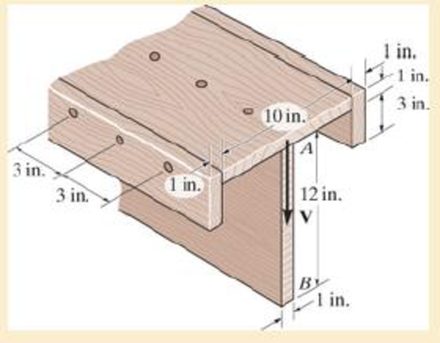
The beam is fabricated from four boards nailed together as shown. Determine the shear force each nail along the sides C and the top D must resist if the nails are uniformly spaced at s=3 in. The beam is subjected to a shear of V=4.5 kip.
The shear force
The shear force
Answer to Problem 7.1RP
The shear force
The shear force
Explanation of Solution
Given information:
The shear force is
The uniform nail spacing is 3 in.
Calculation:
Sketch the diagram of the T section as shown in Figure 1.
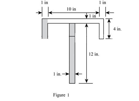
Refer Figure 1,
The area of the beam is the sum of area of three rectangles 1, 2, and 3.
The dimensions of rectangle 1 as width
The dimensions of rectangle 2 as width
The dimensions of rectangle 2 as width
Find the value of area section 1 as shown below:
Substitute 10 in. for
Find the value of area section 2 as shown below:
Substitute 4 in. for
Find the value of area section 3 as shown below:
Substitute 12 in. for
Calculate the centroid of
Here,
Substitute
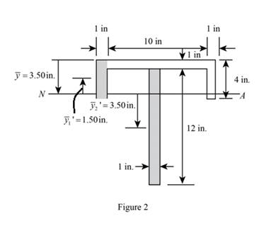
Sketch the diagram of
Calculate the moment of inertia of the beam (I) as follows:
Refer to Figure 2:
The value of
The value of
The value of
Substitute 10 in. for
Calculate the first moment area
Here,
Refer to Figure 2.
The value of
Substitute
Calculate the first moment area
Here,
Refer to Figure 2.
The value of
Substitute
Show the formula for shear flow
Here, V is the shear force, I is the moment of inertia, and
Substitute
Show the formula for shear flow
Here, V is the shear force, I is the moment of inertia, and
Substitute
Calculate the shear force
Here, s is the spacing and
Substitute
Hence, the shear force
Calculate the shear force
Here, s is the spacing and
Substitute
Hence, the shear force
Want to see more full solutions like this?
Chapter 7 Solutions
MECHANICS OF MATERIALS (LOOSE)-W/ACCESS


- 20 mm 20 mm 4. The simply supported beam on the right is built up from three boards by nailing them together as shown. If P = 12 kN, determine the maximum allowable spacing s of the nails to support the load, if each nail can resist a shear force of 1.5 kN. 1 m m B 100 mm 25 mm- 25 mm 200 mm 25 mmarrow_forwardDetermine the maximum shear stress acting in the fiberglass beam at the section where the internal shears force is maximum. (t1=15 mm, t2=20 mm, h=150 mm, b=50mm)arrow_forwardBelow is the shear diagram and the cross-section of a built-up beam. The allowable shear load on the bolts is 1000 N. Dimension a is 50 mm. Determine the largest allowable spacing of the bolts. Sheardiagram: 400 N Cross-section: bolt a -600N NZ.arrow_forward
- A |100 lb B +2+ 4 ft - 180 lb с - 3 -arrow_forwardThe double-web girder is constructed from two plywood sheets that are secured to wood members at its top and bottom. The allowable bending stress for the wood is σallow = 8 ksi and the allowable shear stress is τallow = 3 ksi. The fasteners are spaced s = 6 in. and each fastener can support 400 lb in single shear. Determine the maximum load P that can be applied to the beam.arrow_forwardThe H-beam is subjected to a shear of V = 80 kN. Sketch the shear-stress distribution acting along with one of its side segments. Indicate all peak values.arrow_forward
- Two identical 20-mm-thick plates are bolted to the top and bottom flange to form the built-up beam. If the beam is subjected to a shear force of V = 300 kN, determine the maximum spacing s of the bolts to the nearest mm if eachbolt has a shear strength of 30 kN.arrow_forward1 Determine the location e of the shear center, point O, for the thin-walled member having the cross section shown. The member segments have the same thickness t-5 mm (b30 mm, d=100 mm). |45° 0. 45°arrow_forwardThe beam is subjected to a shear of V=39 kN V=39 kN. Set w=200 mm w=200 mm Part A Determine the web's shear stress at A. Part B Determine the web's shear stress at B.arrow_forward
- 4. If P = 20KN, determine the shear stress developed in pins at point A and C. The pins are subjected to double shear as shown, and each has a diameter of 18mm 30° ? 'B -2 m- + 2 m -2 m 5. The strut is glued to the horizontal member at surface AB. If the strut has thickness of 25mm and the glue can withstand an average shear stress of 600kPa, determine the maximum force P that can be applied strut. 50 mm. 60° Barrow_forwardA wide flange beam as shown below is subjected to a shear force V. Using the dimensions of the cross section, determine the following quantities: a. τmax in the webb. τmin in the webc. τmax/ τaverage of the webarrow_forwardDetermine the internal shear force at a location of x = 0.3 m for the following beam in kN. 3m 8 kN 4 m Xarrow_forward
 Elements Of ElectromagneticsMechanical EngineeringISBN:9780190698614Author:Sadiku, Matthew N. O.Publisher:Oxford University Press
 Mechanics of Materials (10th Edition)Mechanical EngineeringISBN:9780134319650Author:Russell C. HibbelerPublisher:PEARSON
 Thermodynamics: An Engineering ApproachMechanical EngineeringISBN:9781259822674Author:Yunus A. Cengel Dr., Michael A. BolesPublisher:McGraw-Hill Education
 Control Systems EngineeringMechanical EngineeringISBN:9781118170519Author:Norman S. NisePublisher:WILEY
 Mechanics of Materials (MindTap Course List)Mechanical EngineeringISBN:9781337093347Author:Barry J. Goodno, James M. GerePublisher:Cengage Learning
 Engineering Mechanics: StaticsMechanical EngineeringISBN:9781118807330Author:James L. Meriam, L. G. Kraige, J. N. BoltonPublisher:WILEY