
INTERNATIONAL EDITION---Engineering Mechanics: Statics, 14th edition (SI unit)
14th Edition
ISBN: 9780133918922
Author: Russell C. Hibbeler
Publisher: PEARSON
expand_more
expand_more
format_list_bulleted
Concept explainers
Videos
Textbook Question
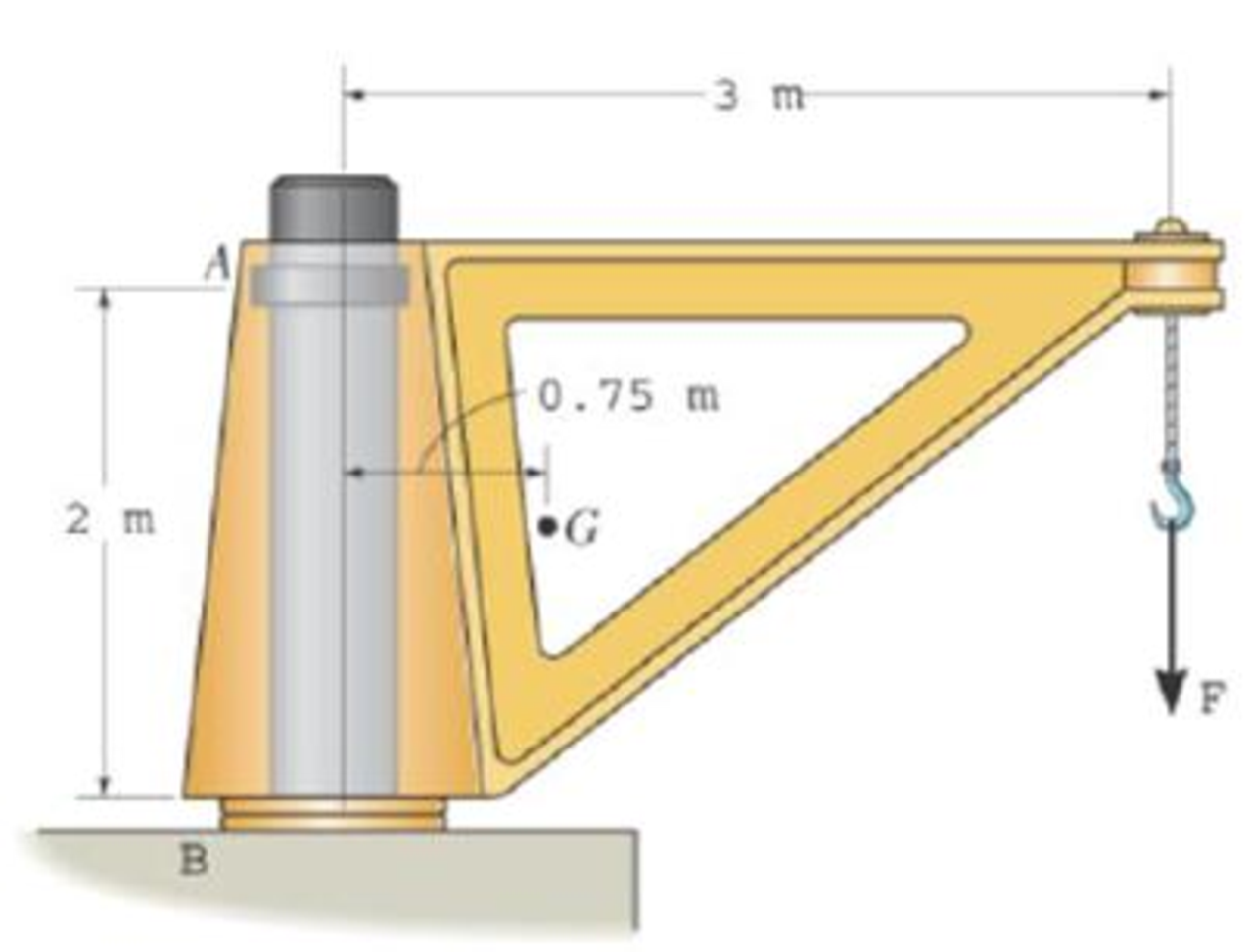
Chapter 5.4, Problem 34P
The dimensions of a jib crane, which is manufactured by the Basick Co., are given in the figure The crane has a mass of 800 kg and a center of mass at G. The bearing at A is a journal bearing and can support a horizontal force, whereas the bearing at B is a thrust bearing that supports both horizontal and vertical components. Determine the maximum load F that can be suspended from its end. If the selected bearings at A and B can sustain a maximum resultant load of 24 kN and 34 kN, respectively.
Expert Solution & Answer
Want to see the full answer?
Check out a sample textbook solution
Students have asked these similar questions
The wheels, axle, and handles of a wheelbarrow W=62N. The load chamber and its contents weigh Wl=575N. The drawing chose leave to Forsyth and different wheelbarrow designs to support the wheelbarrow and equilibrium the man's hands apply a force to the handles that is directly vertically upward. consider the rotational axis at the point where the tire contacts the ground, directed perpendicular to the plane of the paper. Find the magnitude of the Man's force for both designs
The round stepped shaft (diameters d and D) shown below is a design for an exoplanet rover
wheel axle. Assuming the wheel is stuck, a torque from the motor is transmitted to the axle
but it is not rotating. The reaction of the weight of the rover on the ground and the torque
the wheel applies to the ground are represented by the force F acting in the center of the
wheel hub (not shown) at point C. There is a sharp fillet at B with radius r shown below.
Bearings are shown at point A and next to point B. You may assume the bearing at B resists the
bending moment caused by the force F and acts like a fixed reaction.
В
A
L2
L1
T
L3 -
ØD
Ød
R. r
F
SUBMIT ANSWERS HERE:
Paramete
Parameter
Value
Value
SUT (tension)
400 MPa | L1
400 mm
Suc
(Compression)
600 Мра L2
200 mm
Sy
380 MPа L3
100 mm
600 N-m ø d
40 mm
F
0.2 kN ø D
55 mm
R. r
8 mm
4/6- Frames & Machines / Charpente et Mécanisme
Sample Problem / Exemple (4-6)
The frame supports the 400-kg load in the manner shown. Neglect the weights of the
members compared with the forces induced by the load and compute the horizontal and
vertical components of all forces acting on each of the members.
↑
1.5 m
0.5 m
Тв
1.5 m
1.5 m
✓
C
A
3 m
-2 m
E
F
0.5 m
400 kg
La structure supporte une charge de 400 kg de la façon représentée. Négligez
les poids des barres par rapport aux forces développées par la charge et calculez
les composantes horizontales et verticales de toutes les forces qui agissent sur
chacune des barres.
Chapter 5 Solutions
INTERNATIONAL EDITION---Engineering Mechanics: Statics, 14th edition (SI unit)
Ch. 5.2 - Draw the free-body diagram for the following...Ch. 5.2 - Draw the free-body diagram for the following...Ch. 5.2 - Draw the free-body diagram for the following...Ch. 5.2 - Draw the free-body diagram for the following...Ch. 5.2 - Draw the free-body diagram for the following...Ch. 5.2 - Draw the free-body diagram for the following...Ch. 5.2 - Draw the free-body diagram for the following...Ch. 5.2 - Draw the free-body diagram for the following...Ch. 5.2 - Draw the free-body diagram for the following...Ch. 5.4 - Draw the free body diagram of each object. Prob....
Ch. 5.4 - Determine the horizontal and vertical components...Ch. 5.4 - Determine the horizontal and vertical components...Ch. 5.4 - The truss is supported by a pin at A and a roller...Ch. 5.4 - Determine the components of reaction at the fixed...Ch. 5.4 - The 25 kg bar has a center of mass at G. If it is...Ch. 5.4 - Determine the reactions at the smooth contact...Ch. 5.4 - Determine the components of the support reactions...Ch. 5.4 - Determine the reactions at the supports. Prob....Ch. 5.4 - Determine the horizontal and vertical components...Ch. 5.4 - Determine the reactions at the supports. Prob....Ch. 5.4 - Determine the reactions at the supports. Prob....Ch. 5.4 - Determine the reactions at the supports. Prob....Ch. 5.4 - Determine the tension in the cable and the...Ch. 5.4 - The man attempts to a up port the toad of boards...Ch. 5.4 - Determine the components of reaction at the...Ch. 5.4 - The man has a weight W and stands at the center of...Ch. 5.4 - A uniform glass rod having a length L is placed in...Ch. 5.4 - The uniform rod AB has a mass of 40 kg. Determine...Ch. 5.4 - If the intensity of the distributed load acting on...Ch. 5.4 - If the roller at A and the pin at B can support a...Ch. 5.4 - The relay regulates voltage and current. Determine...Ch. 5.4 - Determine the reactions on the bent rod which is...Ch. 5.4 - The mobile crane is symmetrically supported by two...Ch. 5.4 - Determine the reactions acting on the smooth...Ch. 5.4 - A linear torsional spring deforms such that an...Ch. 5.4 - Determine the force P needed to pull the 50-kg...Ch. 5.4 - Determine the magnitude and direction of the...Ch. 5.4 - The operation of the fuel pump for an automobile...Ch. 5.4 - Determine the magnitude of force at the pin A and...Ch. 5.4 - The dimensions of a jib crane, which is...Ch. 5.4 - The dimensions of a jib crane, which is...Ch. 5.4 - The smooth pipe rests against the opening at the...Ch. 5.4 - The beam of negligible weight is supported...Ch. 5.4 - The cantilevered jib crane is used to support the...Ch. 5.4 - The cantilevered jib crane is used to support the...Ch. 5.4 - The bar of negligible weight is supported by two...Ch. 5.4 - Determine the stiffness k of each spring so that...Ch. 5.4 - The bulk head AD Is subjected to both water and...Ch. 5.4 - The boom supports the two vertical loads. Neglect...Ch. 5.4 - The boom is intended to support two vertical loads...Ch. 5.4 - The 10-kg uniform rod is pinned at end A. If It is...Ch. 5.4 - If the truck and its contents have a mass of 50 kg...Ch. 5.4 - Three uniform books each having a weight W and...Ch. 5.4 - Determine the reactions at the pin A and the...Ch. 5.4 - If rope BC will fail when the tension becomes 50...Ch. 5.4 - The rigid metal strip of negligible weight is used...Ch. 5.4 - The rigid metal strip of negligible weight is used...Ch. 5.4 - The cantilever footing is used to support a wail...Ch. 5.4 - The uniform beam has a weight Wand length l and is...Ch. 5.4 - A boy stands out at the end of the diving board,...Ch. 5.4 - The 30-N uniform rod has a length of l = 1 m. If s...Ch. 5.4 - The uniform rod has a length I and weight W. It is...Ch. 5.4 - I he uniform rod of length L and weight W is...Ch. 5.4 - Assuming that the foundation exerts a linearly...Ch. 5.4 - Assuming that the foundation exerts a linearly...Ch. 5.4 - If it is also subjected to a couple moment of 100...Ch. 5.4 - Determine the distance d for placement of the load...Ch. 5.4 - If d = 1 m, and = 30, determine me normal...Ch. 5.4 - The man attempts to pull the tour wheeler up the...Ch. 5.4 - Where is the best place to arrange most of the...Ch. 5.7 - Draw the free-body diagram of each object.Ch. 5.7 - In each case, write the moment equations about the...Ch. 5.7 - The uniform plate has a weight of 500 lb....Ch. 5.7 - Determine the reactions at the roller support A,...Ch. 5.7 - The rod is supported by smooth journal bearings at...Ch. 5.7 - Determine the support reactions at the smooth...Ch. 5.7 - Determine the force developed in the short link...Ch. 5.7 - Determine the components of reaction that the...Ch. 5.7 - Determine the tension each rope and the force that...Ch. 5.7 - If these components have weights WA = 45000 Wa =...Ch. 5.7 - Determine the components of reaction at the fixed...Ch. 5.7 - Determine the vertical reactions at the wheels C...Ch. 5.7 - Determine the components of reaction at A, the...Ch. 5.7 - Determine the tension in each of the three...Ch. 5.7 - Determine the components of reaction at hinges A...Ch. 5.7 - Determine me tension in each cable and the...Ch. 5.7 - The cables are attached to a smooth collar ring at...Ch. 5.7 - Determine the components of reaction at the...Ch. 5.7 - Determine the components of reaction at the...Ch. 5.7 - Determine the components of reaction at the...Ch. 5.7 - Determine the magnitude of F which will cause the...Ch. 5.7 - Determine the components of reaction at A and the...Ch. 5.7 - Determine the components of reaction at these...Ch. 5.7 - Determine the components or reaction at these...Ch. 5.7 - Compute the x, y, z components of reaction at the...Ch. 5.7 - Determine the magnitude of F2 which will cause the...Ch. 5.7 - At A the connection is with a ball-and-socket....Ch. 5.7 - If it is supported by a ball-and-socket joint at C...Ch. 5.7 - Determine the x, y, z components of reaction at...Ch. 5.7 - Determine the horizontal tension T in the belt on...Ch. 5.7 - Determine the horizontal tension T in the belt on...Ch. 5.7 - Determine the components of reaction at A and the...Ch. 5.7 - If the roller at 8 can sustain a maximum load of 3...Ch. 5.7 - Determine the reactions at the supports A and B...Ch. 5.7 - Determine the normal reaction at the roller A and...Ch. 5.7 - Determine the horizontal and vertical components...Ch. 5.7 - Determine the x, y, z components of reaction at...Ch. 5.7 - Determine the horizontal equilibrium force P that...Ch. 5.7 - Determine the x, y, z components of reaction at...Ch. 5.7 - Determine the x and z components of reaction at...
Knowledge Booster


Learn more about
Need a deep-dive on the concept behind this application? Look no further. Learn more about this topic, mechanical-engineering and related others by exploring similar questions and additional content below.Similar questions
- The figure shows a wire cutter. Determine the cutting force on the wire at A when the 75-N forces are applied to the handgrips. (Hint: The horizontal components of pin forces at B and D are zero due to symmetry.)arrow_forwardThe homogeneous plate of weight W is supported by a ball-and-socket joint at D and three wires. Draw the FBD of the plate and count the unknowns.arrow_forwardThe homogeneous bar AB weighs 25 lb. Determine the magnitudes of the forces acting on the bar at A and B. Neglect friction.arrow_forward
- Repeat Problem 11.2-3 assuming that R= 10 kN · m/rad and L = 2 m.arrow_forwardThe linkage is made of two homogenous bars of weights shown in the figure. Determine the horizontal force P required to hold the linkage in the position shown.arrow_forwardThe figure shows a three-pin arch. Determine the horizontal component of the pin reaction at A caused by the applied force P.arrow_forward
- A force of 1000 lb is applied to the 600-lb horizontal beam supported by a hinge at A and a roller at B on a smooth surface. If the pin support at A suddenly fails, calculate the magnitude of the force of the roller at B acting on the beam at that instant, by modelling the beam as a uniform slender bar. Present your answer in lb using 3 significant figures. 4 13 1000 lb -8 ft- B -2 ft-arrow_forwardThe uniform bar AB weighing 240 lb is mounted as shown in the figure upon a carriage weighing 480 lb. The center of gravity of the carriage is at C midway between the wheels. If P = 180 lb and there is no frictional resistance at the wheels, find the value of R1arrow_forwardThe uniform 16-kg plate is welded to the vertical shaft, which is supported by bearings A and B. Calculate the magnitude of the force supported by bearing B during application of the 100-N-m couple to the shaft. The cable from C to D prevents the plate and shaft from turning and the weight of the assembly is carried entirely by bearing A. 220 mm: 100 N-m) B 170 mm 80 mm 600 mm D 480 mmarrow_forward
- a) Determine the maximum mass of block A to maintain equilibrium. b) Calculate the corresponding tensile forces (T1, T2, T3, T4, and T5) in the five segments of the cable indicated in the figure. The centroid of Block B (base: 3a, height: 4a) is located at G. Use g=9.81 m/s². Draw all necessary diagrams and indicate the direction of the impending motion. Additional data are provided below. Hint: Check for slipping, and tipping at points L and R of block B. P = 70 N $ = 20° Parameter: WB = 84.6800 N HB = 0.2645 H12 1 A a = 40° a = 9 cm ठ H34 (3) H23 H45 0 = 50° 12 M23 34 = 0.15 a L B B = 30° μ45= 0.23 G R 22 Parrow_forwardQuestion 3) The position of the head and neck and the forces acting on the head are shown in the figure. The center of gravity of the head of mass m=8 kg is located at point C. The joint reaction force of FJ=147 N, which makes an angle of α= 42° with the vertical from the point B, is acting on the skull by the neck extensor muscles. The center of the atlantooccipital joint is located at point B. For this flexion position of the head, FM neck muscle force, which makes an angle of γ with the horizontal from the A point, is effective. (Take the gravitational acceleration g as 9.81 m/s2). Accordingly; a) Calculate the angle γ of the FM muscle strength with the horizontal. b) Calculate the FM muscle strength. (Write your result in N.) Answerarrow_forwardQuestion 3) The position of the head and neck and the forces acting on the head are shown in the figure. The center of gravity of the head of mass m=8 kg is located at point C. Neck muscle strength of FM=130 N, which makes an angle of γ=65° with the vertical from the B point to the skull, is affected by the neck extensor muscles. The center of the atlantooccipital joint is located at point B. For this flexion position of the head, the FJ joint reaction force, which makes an α angle with the horizontal from point A, acts. (Take the gravitational acceleration g as 9.81 m/s2). Accordingly; a) Calculate the angle α of the FJ joint reaction force with the horizontal. Response b) Calculate the FJ joint reaction force. (Write your result in N.) Answerarrow_forward
arrow_back_ios
arrow_forward_ios
Recommended textbooks for you
 International Edition---engineering Mechanics: St...Mechanical EngineeringISBN:9781305501607Author:Andrew Pytel And Jaan KiusalaasPublisher:CENGAGE L
 Mechanics of Materials (MindTap Course List)Mechanical EngineeringISBN:9781337093347Author:Barry J. Goodno, James M. GerePublisher:Cengage Learning
International Edition---engineering Mechanics: St...
Mechanical Engineering
ISBN:9781305501607
Author:Andrew Pytel And Jaan Kiusalaas
Publisher:CENGAGE L
Mechanics of Materials (MindTap Course List)
Mechanical Engineering
ISBN:9781337093347
Author:Barry J. Goodno, James M. Gere
Publisher:Cengage Learning
EVERYTHING on Axial Loading Normal Stress in 10 MINUTES - Mechanics of Materials; Author: Less Boring Lectures;https://www.youtube.com/watch?v=jQ-fNqZWrNg;License: Standard YouTube License, CC-BY