
Mechanics of Materials, 7th Edition
7th Edition
ISBN: 9780073398235
Author: Ferdinand P. Beer, E. Russell Johnston Jr., John T. DeWolf, David F. Mazurek
Publisher: McGraw-Hill Education
expand_more
expand_more
format_list_bulleted
Videos
Textbook Question
Chapter 5.3, Problem 94P
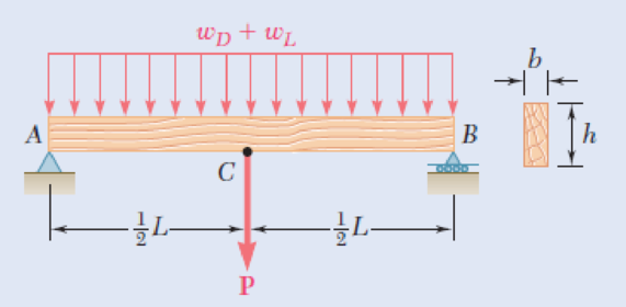
A roof structure consists of plywood and roofing material supported by several timber beams of length L = 16 m. The dead load carried by each beam, including the estimated weight of the beam, can be represented by a uniformly distributed load wD = 350 N/m. The live load consists of a snow load, represented by a uniformly distributed load wL = 600 N/m, and a 6-kN concentrated load P applied at the midpoint C of each beam. Knowing that the ultimate strength for the timber used is σU = 50 MPa and that the width of the beam is b = 75 mm, determine the minimum allowable depth h of the beams, using LRFD with the load factors γD = 1.2, γL = 1.6 and the resistance factor ϕ = 0.9.
Fig. P5.94
Expert Solution & Answer
Want to see the full answer?
Check out a sample textbook solution
Students have asked these similar questions
A beam ABCD, 6 m long, is simply-supported at the right-hand end D and at a point B 1 m from the left hand end A. It carries a
vertical load of 10 kN at A, a second concentrated load of 20 kN at C, 3 m from D, and a uniformly distributed load of 10 kN/m
between C and D. Determine the position and magnitude of the maximum deflection if E = 208 GN/m2 and I = 35 x10^-6 m4.
2. A cover-plate beam is made up of an I-Beam section with 300 mm x 12 mm plates attached to the top
and bottom flanges and is fastened by two rows of 20 mm rivets. The beam is simply supported over a
span of 6m and carries a uniformly distributed load of 270 kN/m including its own weight.
a. Determine the distance from the centroid of the cover plate to the neutral axis of the built-up
section.
b. Determine the moment of inertia of the built-up section about its neutral axis.
c. Determine the maximum flexural stress of the built-up section.
200 mm
30 mm
310 mm
30 mm
30 mm
Q1. (A). A 25mm square cross-section bar of length 300mm carries an axial
compressive load of 50kN. Determine the stress set up in the bar and its change of
length when the load is applied. For the bar material E= 200 GN/m².
Q2. A beam AB, 1.2 m long, is simply-supported at its ends A and B and carries
two concentrated loads, one of 10 kN at C, the other 15 kN at D. Point C is 0.4
m from A, point D is 1 m from A. Draw the S.F. and B.M. diagrams for the
beam.
Q3. A solid steel shaft (A) of 50 mm diameter rotates at 250 rev/min. Find the
greatest power that can be transmitted for a limiting shearing stress of 60
MN/m2 in the steel.
Chapter 5 Solutions
Mechanics of Materials, 7th Edition
Ch. 5.1 - 5.1 through 5.6 For the beam and loading shown,...Ch. 5.1 - 5.1 through 5.6 For the beam and loading shown,...Ch. 5.1 - 5.1 through 5.6 For the beam and loading shown,...Ch. 5.1 - 5.1 through 5.6 For the beam and loading shown,...Ch. 5.1 - 5.1 through 5.6 For the beam and loading shown,...Ch. 5.1 - 5.1 through 5.6 For the beam and loading shown,...Ch. 5.1 - 5.7 and 5.8 Draw the shear and bending-moment...Ch. 5.1 - 5.7 and 5.8 Draw the shear and bending-moment...Ch. 5.1 - 5.9 and 5.10 Draw the shear and bending-moment...Ch. 5.1 - 5.9 and 5.10 Draw the shear and bending-moment...
Ch. 5.1 - 5.11 and 5.12 Draw the shear and bending-moment...Ch. 5.1 - 5.11 and 5.12 Draw the shear and bending-moment...Ch. 5.1 - 5.13 and 5.14 Assuming that the reaction of the...Ch. 5.1 - 5.13 and 5.14 Assuming that the reaction of the...Ch. 5.1 - 5.15 and 5.16 For the beam and loading shown,...Ch. 5.1 - 5.15 and 5.16 For the beam and loading shown,...Ch. 5.1 - For the beam and loading shown, determine the...Ch. 5.1 - For the beam and loading shown, determine the...Ch. 5.1 - 5.19 and 5.20 For the beam and loading shown,...Ch. 5.1 - 5.19 and 5.20 For the beam and loading shown,...Ch. 5.1 - Draw the shear and bending-moment diagrams for the...Ch. 5.1 - 5.22 and 5.23 Draw the shear and bending-moment...Ch. 5.1 - 5.22 and 5.23 Draw the shear and bending-moment...Ch. 5.1 - 5.24 and 5.25 Draw the shear and bending-moment...Ch. 5.1 - 5.24 and 5.25 Draw the shear and bending-moment...Ch. 5.1 - Knowing that W = 12 kN, draw the shear and...Ch. 5.1 - Determine (a) the magnitude of the counterweight W...Ch. 5.1 - Determine (a) the distance a for which the...Ch. 5.1 - Knowing that P = Q = 480 N, determine (a) the...Ch. 5.1 - Solve Prob. 5.29, assuming that P = 480 N and Q =...Ch. 5.1 - Determine (a) the distance a for which the...Ch. 5.1 - A solid steel rod of diameter d is supported as...Ch. 5.1 - A solid steel bar has a square cross section of...Ch. 5.2 - Using the method of Sec. 5.2, solve Prob. 5.1a....Ch. 5.2 - Using the method of Sec. 5.2, solve Prob. 5.2a....Ch. 5.2 - Prob. 36PCh. 5.2 - Prob. 37PCh. 5.2 - Using the method of Sec. 5.2, solve Prob. 5.5a....Ch. 5.2 - Using the method of Sec. 5.2, solve Prob. 5.6a....Ch. 5.2 - Using the method of Sec. 5.2, solve Prob. 5.7. 5.7...Ch. 5.2 - Using the method of Sec. 5.2, solve Prob. 5.8. 5.7...Ch. 5.2 - Prob. 42PCh. 5.2 - Using the method of Sec. 5.2, solve Prob. 5.10....Ch. 5.2 - 5.44 and 5.45 Draw the shear and bending-moment...Ch. 5.2 - 5.44 and 5.45 Draw the shear and bending-moment...Ch. 5.2 - Prob. 46PCh. 5.2 - Prob. 47PCh. 5.2 - Prob. 48PCh. 5.2 - Using the method of Sec. 5.2, solve Prob. 5.20....Ch. 5.2 - 5.50 and 5.51 Determine (a) the equations of the...Ch. 5.2 - 5.50 and 5.51 Determine (a) the equations of the...Ch. 5.2 - 5.52 and 5.53 Determine (a) the equations of the...Ch. 5.2 - 5.52 and 5.53 Determine (a) the equations of the...Ch. 5.2 - 5.54 and 5.55 Draw the shear and bending-moment...Ch. 5.2 - 5.54 and 5.55 Draw the shear and bending-moment...Ch. 5.2 - 5.56 and 5.57 Draw the shear and bending-moment...Ch. 5.2 - 5.56 and 5.57 Draw the shear and bending-moment...Ch. 5.2 - 5.58 and 5.59 Draw the shear and bending-moment...Ch. 5.2 - 5.58 and 5.59 Draw the shear and bending-moment...Ch. 5.2 - Knowing that beam AB is in equilibrium under the...Ch. 5.2 - Knowing that beam AB is in equilibrium under the...Ch. 5.2 - The beam AB supports two concentrated loads P and...Ch. 5.2 - The beam AB supports a uniformly distributed load...Ch. 5.2 - Beam AB supports a uniformly distributed load of 2...Ch. 5.3 - 5.65 and 5.66 For the beam and loading shown,...Ch. 5.3 - 5.65 and 5.66 For the beam and loading shown,...Ch. 5.3 - 5.67 and 5.68 For the beam and loading shown,...Ch. 5.3 - 5.67 and 5.68 For the beam and loading shown,...Ch. 5.3 - 5.69 and 5.70 For the beam and loading shown,...Ch. 5.3 - 5.69 and 5.70 For the beam and loading shown,...Ch. 5.3 - 5.71 and 5.72 Knowing that the allowable normal...Ch. 5.3 - 5.71 and 5.72 Knowing that the allowable normal...Ch. 5.3 - 5.73 and 5.74 Knowing that the allowable normal...Ch. 5.3 - 5.73 and 5.74 Knowing that the allowable normal...Ch. 5.3 - 5.75 and 5.76 Knowing that the allowable normal...Ch. 5.3 - 5.75 and 5.76 Knowing that the allowable normal...Ch. 5.3 - 5.77 and 5.78 Knowing that the allowable normal...Ch. 5.3 - 5.77 and 5.78 Knowing that the allowable normal...Ch. 5.3 - A steel pipe of 100-mm diameter is to support the...Ch. 5.3 - Two metric rolled-steel channels are to be welded...Ch. 5.3 - Two rolled-steel channels are to be welded back to...Ch. 5.3 - Two L4 3 rolled-steel angles are bolted together...Ch. 5.3 - Assuming the upward reaction of the ground to be...Ch. 5.3 - Assuming the upward reaction of the ground to be...Ch. 5.3 - Determine the largest permissible distributed load...Ch. 5.3 - Solve Prob. 5.85, assuming that the cross section...Ch. 5.3 - Determine the largest permissible value of P for...Ch. 5.3 - Solve Prob. 5.87, assuming that the T-shaped beam...Ch. 5.3 - Beams AB, BC, and CD have the cross section shown...Ch. 5.3 - Beams AB, BC, and CD have the cross section shown...Ch. 5.3 - Each of the three rolled-steel beams shown...Ch. 5.3 - A 54-kip load is to be supported at the center of...Ch. 5.3 - A uniformly distributed load of 66 kN/m is to be...Ch. 5.3 - A roof structure consists of plywood and roofing...Ch. 5.3 - Solve Prob. 5.94, assuming that the 6-kN...Ch. 5.3 - Prob. 96PCh. 5.3 - Assuming that the front and rear axle loads remain...Ch. 5.4 - 5.98 through 5.100 (a) Using singularity...Ch. 5.4 - 5.98 through 5.100 (a) Using singularity...Ch. 5.4 - 5.98 through 5.100 (a) Using singularity...Ch. 5.4 - 5.101 through 5.103 (a) Using singularity...Ch. 5.4 - Prob. 102PCh. 5.4 - Prob. 103PCh. 5.4 - Prob. 104PCh. 5.4 - Prob. 105PCh. 5.4 - Prob. 106PCh. 5.4 - Prob. 107PCh. 5.4 - Prob. 108PCh. 5.4 - Prob. 109PCh. 5.4 - Prob. 110PCh. 5.4 - Prob. 111PCh. 5.4 - Prob. 112PCh. 5.4 - 5.112 and 5.113 (a) Using singularity functions,...Ch. 5.4 - Prob. 114PCh. 5.4 - 5.114 and 5.115 A beam is being designed to be...Ch. 5.4 - 5.116 and 5.117 A timber beam is being designed to...Ch. 5.4 - Prob. 117PCh. 5.4 - Prob. 118PCh. 5.4 - Prob. 119PCh. 5.4 - 5.118 through 5.121 Using a computer and step...Ch. 5.4 - Prob. 121PCh. 5.4 - 5.122 and 5.123 For the beam and loading shown and...Ch. 5.4 - 5.122 and 5.123 For the beam and loading shown and...Ch. 5.4 - 5.124 and 5.125 For the beam and loading shown and...Ch. 5.4 - Prob. 125PCh. 5.5 - 5.126 and 5.127 The beam AB, consisting of a...Ch. 5.5 - Prob. 127PCh. 5.5 - 5.128 and 5.129 The beam AB, consisting of a...Ch. 5.5 - 5.128 and 5.129 The beam AB, consisting of a...Ch. 5.5 - Prob. 130PCh. 5.5 - Prob. 131PCh. 5.5 - Prob. 132PCh. 5.5 - 5.132 and 5.133 A preliminary design on the use of...Ch. 5.5 - Prob. 134PCh. 5.5 - Prob. 135PCh. 5.5 - Prob. 136PCh. 5.5 - Prob. 137PCh. 5.5 - Prob. 138PCh. 5.5 - Prob. 139PCh. 5.5 - Assuming that the length and width of the cover...Ch. 5.5 - Two cover plates, each 12 in. thick, are welded to...Ch. 5.5 - Two cover plates, each 12 in. thick, are welded to...Ch. 5.5 - Prob. 143PCh. 5.5 - Prob. 144PCh. 5.5 - Two cover plates, each 7.5 mm thick, are welded to...Ch. 5.5 - Prob. 146PCh. 5.5 - Prob. 147PCh. 5.5 - For the tapered beam shown, determine (a) the...Ch. 5.5 - Prob. 149PCh. 5.5 - Prob. 150PCh. 5.5 - Prob. 151PCh. 5 - Draw the shear and bending-moment diagrams for the...Ch. 5 - Draw the shear and bending-moment diagrams for the...Ch. 5 - Determine (a) the distance a for which the...Ch. 5 - For the beam and loading shown, determine the...Ch. 5 - Draw the shear and bending-moment diagrams for the...Ch. 5 - Beam AB, of length L and square cross section of...Ch. 5 - Prob. 158RPCh. 5 - Knowing that the allowable normal stress for the...Ch. 5 - Prob. 160RPCh. 5 - (a) Using singularity functions, find the...Ch. 5 - Prob. 162RPCh. 5 - Prob. 163RP
Knowledge Booster


Learn more about
Need a deep-dive on the concept behind this application? Look no further. Learn more about this topic, mechanical-engineering and related others by exploring similar questions and additional content below.Similar questions
- In the mechanism shown below, the distributed load W is 200 N/m and the angle e is 55°, knowing that link AB has 1.5cm x 1.5cm cross-section. W B 1.5 m e a 1-What is the average normal stress at section b-b? 546.1 kPa 267.7 kPa 813.8 kPa 779.9 kPa 942.8 kPa Alerearrow_forwardAn annular washer distributes the load P applied to a steel rod to a timber support. The rod's diameter is 22 mm, and the washer's inner diameter is 25 mm, which is larger than the hole's permissible outer diameter. Knowing that the axial normal stress in the steel rod is 35 MPa and the average bearing stress between the washer and the timber must not exceed 5 MPa, examine the smallest allowed outer diameter, d, of the washer. %3D %3D +22 mm P Figure 4arrow_forwardHomework A timber beam AB of length L and rectangular cross section carries a single concentrated load P at its midpoint C. (a) Show that the ratio Tm/Tm of the maximum values of the shearing and normal stresses in the beam is equal to h/2L, where h and L are, respectively, the depth and the length of the beam. (b) Determine the depth h and the width b of the beam, knowing that L = 2 m, P = 40 kN, 7m = 960 kPa, and om = 12 MPa. |P L/2 - - L/2· A Вarrow_forward
- In the mechanism shown below, the distributed load W is 200 N/m and the angle e is 55", knowing that link AB has 1.5cm x 1.5cm cross-section. W B 1.5 m e 1-What is the average normal stress at section b-b? O 546.1 kPa O 267.7 kPa O 813.8 kPa O 779.9 kPa O 942.8 kPa O Nonearrow_forwardA chain link with a circular cross section of diameter d = 12 mm is subjected to the forces exerted by neighboring links, as illustrated below. Determine: 1) the maximum tensile stress and maximum compressive stress acting on cross section AA'. 2) the distance between the neutral axis and the centroid of cross section AA'. 4800 N 800 N - AA'arrow_forwardPole AB is 12m. long and its weight W = 35kN. It is being lifted using BC and BD. When the pole is tilted at an angle of 60° from the x-axis, the resultant force acts at point A. 'p 2.6 m 3 m 4.5 m 3m 1. Find the tensile force (kN) in cable BC. В. 21.6 A. 22.5 C. 26.1 D. 28.2 2. Find the tensile force (kN) in cable BD. А. 13.1 В. 11.3 С. 14.5 D. 16.1 3. What is the value of the resultant (kN) acting at point A. В. 65.9 А. 69.5 C. 90.6 D. 56.9arrow_forward
- Q1) For the beam with the loading shown, determine the deflection at the center c of the beam. Knowing that the beam is made of steel for which E 200 GPa, and it has a rectangular cross- section of (200 mm x 100 mm). 20 KN 20 KN 100 D 0.75 m 1.2 m Cuf 1m B 200arrow_forwardProblem 5 Rigid member ABC is supported with two links BE and CD which have a cross section area of 230 and 300 mm? respectively. Determine the maximum applied force Q knowing that the maximum movement of point E is 0.45 mm. D Brass E - 105 GPa 230 mm B C E Aluminum E = 70 GPa 150 mm 65 mm 230 mm Area given is for member AB not BE Cross section area of links AB and CD are 230 and 300 mm^2 respectively.arrow_forwardFor the beam and loading shown, use the double-integration method to determine (a) the equation of the elastic curve for the beam, (b) the location of the maximum deflection, and (c) the maximum beam deflection. Assume that El is constant for the beam. Let w = 13 kN/m, L = 4.0 m, E = 180 GPa, and I = 130 x 106 mm“. B L Answer: (b) х %3 m (c) Vmax mmarrow_forward
- A cover-plate beam is made up of an 1-Beam section with 300 mm x 12 mm plates attached to the top and bottom flanges and is fastened by two rows of 20 mm rivets. The beam is simply supported over a span of 6m and carries a uniformly distributed load of 270 kN/m including its own weight. a. Determine the distance from the centroid of the cover plate to the neutral axis of the built-up section. b. Determine the moment of inertia of the built-up section about its neutral axis. c. Determine the maximum flexural stress of the built-up section. 200 mm 30 mm 310 mm 30 mm 30 mmarrow_forwardProblem 1): A circular pipe girder is constructed from 80mm external diameter and 60 mm internal diameter. Three such girders are mounted vertically one at equal angles of a circular horizontal platform which the girders support. The platform is 5 m above ground level and weighs (0.1*B) KN. The platform supports an additional central load of (0.2*B) KN. The weight of the girders may not be neglected. The density of the material from which the girders are constructed is (290*B) kg/m3. Assuming that each girder supports an equal share of the load, determine the compressive stresses set up in the material of each girder:1- At the lower point of the girder.2- At the middle point of the girder.3- At the upper point of the girder. Discuss the above values when the weights of the girders are neglected.Note: B = 39 Problem 2): A 20 mm diameter steel rod passes concentrically through a bronze tube (200+Q) mm long, 50 mm external diameter, and 40 mm internal diameter. The ends of the steel rod…arrow_forwardProblem 04.103 - Steel W-beam loaded with up to three axial loads As many as three axial loads, each of magnitude P= 50 kN, can be applied to the end of a W200 × 31.1 rolled-steel shape. 80 mm- -80 mm 777 Problem 04.103.b - Stress in a flange when only two axial loads are applied Determine the stress at point A if loads are applied at points 1 and 2 only. The stress at point A is MPa.arrow_forward
arrow_back_ios
SEE MORE QUESTIONS
arrow_forward_ios
Recommended textbooks for you
 Elements Of ElectromagneticsMechanical EngineeringISBN:9780190698614Author:Sadiku, Matthew N. O.Publisher:Oxford University Press
 Mechanics of Materials (10th Edition)Mechanical EngineeringISBN:9780134319650Author:Russell C. HibbelerPublisher:PEARSON
 Thermodynamics: An Engineering ApproachMechanical EngineeringISBN:9781259822674Author:Yunus A. Cengel Dr., Michael A. BolesPublisher:McGraw-Hill Education
 Control Systems EngineeringMechanical EngineeringISBN:9781118170519Author:Norman S. NisePublisher:WILEY
 Mechanics of Materials (MindTap Course List)Mechanical EngineeringISBN:9781337093347Author:Barry J. Goodno, James M. GerePublisher:Cengage Learning
 Engineering Mechanics: StaticsMechanical EngineeringISBN:9781118807330Author:James L. Meriam, L. G. Kraige, J. N. BoltonPublisher:WILEY
Elements Of Electromagnetics
Mechanical Engineering
ISBN:9780190698614
Author:Sadiku, Matthew N. O.
Publisher:Oxford University Press
Mechanics of Materials (10th Edition)
Mechanical Engineering
ISBN:9780134319650
Author:Russell C. Hibbeler
Publisher:PEARSON
Thermodynamics: An Engineering Approach
Mechanical Engineering
ISBN:9781259822674
Author:Yunus A. Cengel Dr., Michael A. Boles
Publisher:McGraw-Hill Education
Control Systems Engineering
Mechanical Engineering
ISBN:9781118170519
Author:Norman S. Nise
Publisher:WILEY
Mechanics of Materials (MindTap Course List)
Mechanical Engineering
ISBN:9781337093347
Author:Barry J. Goodno, James M. Gere
Publisher:Cengage Learning
Engineering Mechanics: Statics
Mechanical Engineering
ISBN:9781118807330
Author:James L. Meriam, L. G. Kraige, J. N. Bolton
Publisher:WILEY
An Introduction to Stress and Strain; Author: The Efficient Engineer;https://www.youtube.com/watch?v=aQf6Q8t1FQE;License: Standard YouTube License, CC-BY