
Mechanics of Materials
11th Edition
ISBN: 9780137605460
Author: Russell C. Hibbeler
Publisher: Pearson Education (US)
expand_more
expand_more
format_list_bulleted
Concept explainers
Videos
Textbook Question
Chapter 5.3, Problem 11P
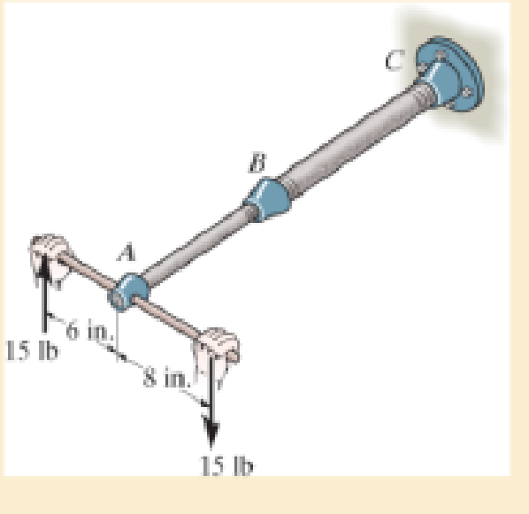
The assembly consists of two sections of galvanized steel pipe connected together using a reducing coupling at B. The smaller pipe has an outer diameter of 0.75 in. and an inner diameter of 0.68 in., whereas the larger pipe has an outer diameter of 1 in. and an inner diameter of 0.86 in. If the pipe is tightly secured to the wall at C, determine the maximum shear stress in each section of the pipe when the couple is applied to the handles of the wrench.
Expert Solution & Answer
Want to see the full answer?
Check out a sample textbook solution
Students have asked these similar questions
The assembly consists of two sections of galvanized steel pipe connected together using a reducing coupling at B. The smaller pipe has an outer diameter of 0.75 in. and an inner diameter of 0.68 in., whereas the larger pipe has an outer diameter of 1 in. and an inner diameter of 0.86 in. If the pipe istightly secured to the wall at C, determine the maximum shear stress in each section of the pipe when the couple is applied to the handles of the wrench.
0-13. The assembly consists of two sections of galvanized
steel pipe connected together using a reducing coupling at B.
The smaller pipe has an outer diameter of 18.75 mm and an
inner diameter of 17 mm, whereas the larger pipe has an outer
diameter of 25 mm and an inner diameter of 215 mm. If the
pipe is tightly secured to the wall at C, determine the maximum
shear stress developed in cach section of the pipe when the
couple shown is applied to the handles of the wrench.
75 N
75 N
The yoke-and-rod connection is subjected to a tensile force P. The end of the 40-mm
diameter rod is embedded inside a wall at a length I of 100 mm using epoxy adhesive. If
the allowable normal stress for the rods is 60 MPa, the allowable shear stress for the 25-
mm diameter pin A is 50 MPa, and the allowable shear stress of the epoxy adhesive is 6
MPa, determine the largest force P that can be applied to the assembly.
Note: Show your calculations for all types of stresses in detail.
40 mm
30 mm
A
25 mm
P.
Chapter 5 Solutions
Mechanics of Materials
Ch. 5.3 - The solid circular shaft is subjected to an...Ch. 5.3 - The hollow circular shaft is subjected to an...Ch. 5.3 - The shaft is hollow from A to B and solid from B...Ch. 5.3 - Determine the maximum shear stress in the...Ch. 5.3 - Determine the maximum shear stress in the shaft at...Ch. 5.3 - Determine the shear stress a: point A on the...Ch. 5.3 - The solid 50-mm-diameter shaft is subjected to the...Ch. 5.3 - The gear motor can develop 3 hp when it turns at...Ch. 5.3 - The solid shaft of radius r is subjected to a...Ch. 5.3 - The solid shaft of radius r is subjected to a...
Ch. 5.3 - Prob. 3PCh. 5.3 - The copper pipe has an outer diameter of 40 mm and...Ch. 5.3 - The copper pipe has an outer diameter of 2.50 in....Ch. 5.3 - The link acts as part of the elevator control for...Ch. 5.3 - The assembly consists of two sections of...Ch. 5.3 - A steel tube having an outer diameter of 2.5 in....Ch. 5.3 - The rod has a diameter of 1 in. and a weight of 10...Ch. 5.3 - The rod has a diameter of 1 in. and a weight of 15...Ch. 5.3 - Prob. 20PCh. 5.3 - The 60-mm-diameter solid shaft is subjected to the...Ch. 5.3 - The 60-mm-diameter solid shaft is subjected to the...Ch. 5.3 - The solid shaft is subjected to the distributed...Ch. 5.3 - If the tube is made from a material having an...Ch. 5.3 - Prob. 29PCh. 5.3 - The motor delivers 50 hp while turning at a...Ch. 5.3 - The solid steel shaft AC has a diameter of 25 mm...Ch. 5.3 - Prob. 35PCh. 5.4 - The 60 mm-diameter steel shaft is subjected to the...Ch. 5.4 - Prob. 10FPCh. 5.4 - The hollow 6061-T6 aluminum shaft has an outer and...Ch. 5.4 - A series of gears are mounted on the...Ch. 5.4 - The 80-mm-diameter shaft is made of steel. If it...Ch. 5.4 - The 80-mm-diameter shaft is made of steel. If it...Ch. 5.4 - The propellers of a ship are connected to an A-36...Ch. 5.4 - Show that the maximum shear strain in the shaft is...Ch. 5.4 - Determine the angle of twist of end B with respect...Ch. 5.4 - Determine the maximum allowable torque T. Also,...Ch. 5.4 - If the allowable shear stress is allow = 80 MPa,...Ch. 5.4 - Determine the angle of twist of the end A.Ch. 5.4 - The hydrofoil boat has an A992 steel propeller...Ch. 5.4 - Also, calculate the absolute maximum shear stress...Ch. 5.4 - If a torque of T = 50 N m is applied to the bolt...Ch. 5.4 - If a torque of T= 50N m is applied to the bolt...Ch. 5.4 - If the motor delivers 4 MW of power to the shaft...Ch. 5.4 - Determine the angle of twist at the free end A of...Ch. 5.5 - Gst = 75 GPa.Ch. 5.5 - The shaft is made of L2 tool steel, has a diameter...Ch. 5.5 - Each has a diameter of 25 mm and they are...Ch. 5.5 - Each has a diameter of 25 mm and they are...Ch. 5.5 - It is fixed at its ends and subjected to a torque...Ch. 5.5 - 5–89. Determine the absolute maximum shear stress...Ch. 5.7 - If the yield stress for brass is Y = 205 MPa,...Ch. 5.7 - By what percentage is the shaft of circular cross...Ch. 5.7 - Prob. 97PCh. 5.7 - Also, find the angle of twist of end B. The shaft...Ch. 5.7 - Also, find the corresponding angle of twist at end...Ch. 5.7 - Prob. 110PCh. 5.7 - Determine the average shear stress in the tube if...Ch. 5.7 - By what percentage is the torsional strength...Ch. 5.7 - Prob. 114PCh. 5.7 - Prob. 115PCh. 5.7 - Prob. 119PCh. 5.10 - Prob. 121PCh. 5.10 - If the radius of the fillet weld connecting the...Ch. 5.10 - Prob. 125PCh. 5.10 - Determine the radius of the elastic core produced...Ch. 5.10 - Prob. 128PCh. 5.10 - Determine the torque T needed to form an elastic...Ch. 5.10 - Determine the torque applied to the shaft.Ch. 5.10 - Prob. 131PCh. 5.10 - Determine the ratio of the plastic torque Tp to...Ch. 5.10 - Determine the applied torque T, which subjects the...Ch. 5.10 - Determine the radius of its elastic core if it is...Ch. 5.10 - Plot the shear-stress distribution acting along a...Ch. 5.10 - If the material obeys a shear stress-strain...Ch. 5.10 - It is made of an elastic perfectly plastic...Ch. 5.10 - Prob. 139PCh. 5.10 - Prob. 140PCh. 5.10 - Prob. 142PCh. 5.10 - Prob. 143PCh. 5 - The shaft is made of A992 steel and has an...Ch. 5 - The shaft is made of A992 steel and has an...Ch. 5 - Determine the shear stress at the mean radius p =...Ch. 5 - If the thickness of its 2014-T6-aluminum skin is...Ch. 5 - Determine which shaft geometry will resist the...Ch. 5 - If couple forces P = 3 kip are applied to the...Ch. 5 - If the allowable shear stress for the aluminum is...Ch. 5 - Determine the angle of twist of its end A if it is...Ch. 5 - This motion is caused by the unequal belt tensions...
Knowledge Booster


Learn more about
Need a deep-dive on the concept behind this application? Look no further. Learn more about this topic, mechanical-engineering and related others by exploring similar questions and additional content below.Similar questions
- Q2/ The assembly consists of two sections of galvanized steel pipe connected together using a reducing coupling at B. The smaller pipe has an outer diameter of 0.75 in. and an inner diameter of 0.68 in., whereas the larger pipe has an outer diameter of 1 in. and an inner diameter of 0.86 in. If the pipe is tightly secured to the wall at C, determine the maximum shear stress developed in each section of the pipe when the couple shown is applied to the handles of the wrench. C B 6 in. 17 lb 8 in. 17 lbarrow_forwardThe rows of staples AB contained in the stapler is glued together so that the maximum shear stress the glue can withstand is 12 psi. Determine the maximum force F that must be placed on the plunger in order to shear off a staple from its row and allow it to exit undeformed through the groove at C. The outer dimensions are shown in the figure below. The thickness of the staple is 0.05 in. Assume all the other parts are rigid.arrow_forwardDetermine the shear stress at point B on the web of the cantilevered strut at section a–a.arrow_forward
- The bar AB is supported by a frictionless inclined surface at A and a 7/8-in.-diameter pin at B that is in double shear. Determine the shear stress in the pin when the vertical 2000-lb force is applied. Neglect the weight of the bar.arrow_forwardThe lever is held to the fixed shaft using a taperedpin AB, which has a mean diameter of 6 mm. If a couple isapplied to the lever, determine the average shear stress inthe pin between the pin and lever.arrow_forwardThe lever is held to the fixed shaft using the pin AB. If the couple is applied to the lever, determine the shear force in the pin between the pin and the lever.arrow_forward
- The coupling is used to connect the tWo shafts together. Assuming that the shear stress in the bolls is uniform, determine the number of bolts necessary to make the maximum shear stress in the shaft equal to the sher stress in the bolts Each bolt has a diameter d.arrow_forwardRailroad ties must be designed to resist large shear loadings. If the tie is subjected to the 34-kip rail loadings and an assumed uniformly distributed ground reaction, determine the intensity w for equilibrium, and calculate themaximum shear stress in the tie at section a–a, which is located just to the left of the rail.arrow_forwardIf the allowable shear stress for each of the 10-mm-diameter steel pins at A, B, and C is allow = 90 MPa, and the allowable normal stress for the 13-mm-diameter rod is allow = 150 MPa, determine the largest intensity w of the uniform distributed load that can be suspended from the beam.arrow_forward
- Determine the maximum average shear stress in pin A of the truss. A horizontal force of P = 40 kN is applied to joint C. Each pin has a diameter of 25 mm and is subjected to double shear.arrow_forwardThe assembly is used to support the distributed load of w=500 lb/ft. determine effortnormal in bar BC and the shear stress in pins B and C. The bar has adiameter of 0.40 in. and each of the bolts has a diameter of 0.30 in. Express theanswers in ksi.arrow_forwardThe railcar docklight is supported by the 1/8-in.-diameter pin at A. If the lamp weighs 4.1 lb, and the extension arm AB has a weight of 0.6 lb/ft. 3 ft -1.25 in Part A Determine the average shear stress in the pin needed to support the lamp. Hint:The shear force in the pin is caused by the couple moment required for equilibrium at A. Express your answer to three significant figures and include appropriate units. Value Unitsarrow_forward
arrow_back_ios
SEE MORE QUESTIONS
arrow_forward_ios
Recommended textbooks for you
 Elements Of ElectromagneticsMechanical EngineeringISBN:9780190698614Author:Sadiku, Matthew N. O.Publisher:Oxford University Press
 Mechanics of Materials (10th Edition)Mechanical EngineeringISBN:9780134319650Author:Russell C. HibbelerPublisher:PEARSON
 Thermodynamics: An Engineering ApproachMechanical EngineeringISBN:9781259822674Author:Yunus A. Cengel Dr., Michael A. BolesPublisher:McGraw-Hill Education
 Control Systems EngineeringMechanical EngineeringISBN:9781118170519Author:Norman S. NisePublisher:WILEY
 Mechanics of Materials (MindTap Course List)Mechanical EngineeringISBN:9781337093347Author:Barry J. Goodno, James M. GerePublisher:Cengage Learning
 Engineering Mechanics: StaticsMechanical EngineeringISBN:9781118807330Author:James L. Meriam, L. G. Kraige, J. N. BoltonPublisher:WILEY
Elements Of Electromagnetics
Mechanical Engineering
ISBN:9780190698614
Author:Sadiku, Matthew N. O.
Publisher:Oxford University Press
Mechanics of Materials (10th Edition)
Mechanical Engineering
ISBN:9780134319650
Author:Russell C. Hibbeler
Publisher:PEARSON
Thermodynamics: An Engineering Approach
Mechanical Engineering
ISBN:9781259822674
Author:Yunus A. Cengel Dr., Michael A. Boles
Publisher:McGraw-Hill Education
Control Systems Engineering
Mechanical Engineering
ISBN:9781118170519
Author:Norman S. Nise
Publisher:WILEY
Mechanics of Materials (MindTap Course List)
Mechanical Engineering
ISBN:9781337093347
Author:Barry J. Goodno, James M. Gere
Publisher:Cengage Learning
Engineering Mechanics: Statics
Mechanical Engineering
ISBN:9781118807330
Author:James L. Meriam, L. G. Kraige, J. N. Bolton
Publisher:WILEY
Hand Tools; Author: UCI Media;https://www.youtube.com/watch?v=4o0tqF0jDdo;License: Standard Youtube License