
Fundamentals of Electric Circuits
6th Edition
ISBN: 9780078028229
Author: Charles K Alexander, Matthew Sadiku
Publisher: McGraw-Hill Education
expand_more
expand_more
format_list_bulleted
Videos
Textbook Question
Chapter 3.9, Problem 12PP
For the transistor circuit in Fig. 3.42, let β = 100 and VBE = 0.7 V. Determine vo and VCE.
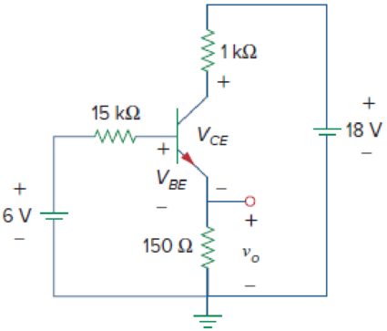
Figure 3.42
Expert Solution & Answer
Want to see the full answer?
Check out a sample textbook solution
Students have asked these similar questions
For the transistor circuit shown below, what is the value of the Vce?
Vcc = +16 V
Ic
Rc
3.9 kN.
R81
C2
62 kN
10 μF
→ B
V CE
+
B = 80
10 µF
V BE E
R82
RE
0.68 kN
CE
50 μF
9.1 kN
A) 8.067 V
B 4.573 V
8.075 V
8.149 V
Question 3.28
An input voltage of 2V rms (measured from base to ground) is applied to the circuit of Fig. 3.21. Its putting that the emitter voltage follows the base voltage exactly and that Vbe (rms)= 0.1 V, Calculate the voltage amplification of the circuit (AV= V0/Vi) and the emitter current for RE= 1kilohms.
For the transistor circuit shown below, what is the value of the VcE?
Vcc
= +16 V
...
Ic
Rc
3.9 kN
R81
C2
62 kN
IB
10 μF
+
В
Vi
V CE
B = 80
+
II
10 µF
V BE E
RB2
RE
20.68 kN
CE
50 μF
9.1 kN
(A) 8.075 V
B) 8.067 V
4.573 V
D) 8.149 V
두
Chapter 3 Solutions
Fundamentals of Electric Circuits
Ch. 3.2 - Figure 3.4 For Practice Prob. 3.1. Obtain the node...Ch. 3.2 - Figure 3.6 For Practice Prob. 3.2. Find the...Ch. 3.3 - Figure 3.11 For Practice Prob. 3.3. Find v and i...Ch. 3.3 - Figure 3.14 For Practice Prob. 3.4. Find v1, v2,...Ch. 3.4 - Practice Problem 3.5 Figure 3.19 For Practice...Ch. 3.4 - Practice Problem 3.6 Figure 3.21 For Practice...Ch. 3.5 - Practice Problem 3.7 Figure 3.25 For Practice...Ch. 3.6 - By inspection, obtain the node-voltage equations...Ch. 3.6 - By inspection, obtain the mesh-current equations...Ch. 3.8 - For the circuit in Fig. 3.33, use PSpice to find...
Ch. 3.8 - Use PSpice to determine currents i1, i2, and i3 in...Ch. 3.9 - For the transistor circuit in Fig. 3.42, let =...Ch. 3.9 - The transistor circuit in Fig. 3.45 has = 80 and...Ch. 3 - At node 1 in the circuit of Fig. 3.46, applying...Ch. 3 - Figure 3.46 For Review Questions 3.1 and 3.2 In...Ch. 3 - For the circuit in Fig. 3.47, v1 and v2 are...Ch. 3 - Figure 3.47 For Review Questions 3.3 and 3.4....Ch. 3 - The circuit i in the circuit of Fig. 3.48 is:...Ch. 3 - Figure 3.48 For Review Questions 3.5 and 3.6....Ch. 3 - In the circuit of Fig. 3.49, current i1 is: (a)4 A...Ch. 3 - Figure 3.49 For Review Questions 3.7 and 3.8....Ch. 3 - The PSpice part name for a current-controlled...Ch. 3 - Which of the following statements are not true of...Ch. 3 - Using Fig. 3.50, design a problem to help other...Ch. 3 - For the circuit in Fig. 3.51, obtain v1 and v2....Ch. 3 - Find the currents I1 through I4 and the voltage vo...Ch. 3 - Given the circuit in Fig. 3.53, calculate the...Ch. 3 - Obtain vo in the circuit of Fig. 3.54. Figure 3.54...Ch. 3 - Solve for V1 in the circuit of Fig. 3.55 using...Ch. 3 - Apply nodal analysis to solve for Vx in the...Ch. 3 - Using nodal analysis, find vo in the circuit of...Ch. 3 - Determine Ib in the circuit in Fig. 3.58 using...Ch. 3 - Prob. 10PCh. 3 - Find Vo and the power dissipated in all the...Ch. 3 - Using nodal analysis, determine Vo in the circuit...Ch. 3 - Calculate v1 and v2 in the circuit of Fig. 3.62...Ch. 3 - Using nodal analysis, find vo in the circuit of...Ch. 3 - Apply nodal analysis to find io and the power...Ch. 3 - Determine voltages v1 through v3 in the circuit of...Ch. 3 - Prob. 17PCh. 3 - Determine the node voltages in the circuit in Fig....Ch. 3 - Use nodal analysis to find v1, v2 and v3 in the...Ch. 3 - For the circuit in Fig. 3.69, find v1, v2, and v3...Ch. 3 - For the circuit in Fig. 3.70, find v1 and v2 using...Ch. 3 - Determine v1 and v2 in the circuit of Fig. 3.71....Ch. 3 - Use nodal analysis to find Vo in the circuit of...Ch. 3 - Use nodal analysis and MATLAB to find Vo in the...Ch. 3 - Use nodal analysis along with MATLAB to determine...Ch. 3 - Calculate the node voltages v1, v2, and v3 in the...Ch. 3 - Use nodal analysis to determine voltages v1, v2,...Ch. 3 - Use MATLAB to find the voltages at nodes a, b, c,...Ch. 3 - Use MATLAB to solve for the node voltages in the...Ch. 3 - Using nodal analysis, find vo and io in the...Ch. 3 - Find the node voltages for the circuit in Fig....Ch. 3 - Obtain the node voltages v1, v2, and v3 in the...Ch. 3 - Which of the circuits in Fig. 3.82 is planar? For...Ch. 3 - Determine which of the circuits in Fig. 3.83 is...Ch. 3 - Figure 3.54 For Prob. 3.5. Rework Prob. 3.5 using...Ch. 3 - Use mesh analysis to obtain ia, ib, and ic in the...Ch. 3 - Using nodal analysis, find vo in the circuit of...Ch. 3 - Apply mesh analysis to the circuit in Fig. 3.85...Ch. 3 - Using Fig. 3.50 from Prob. 3.1, design a problem...Ch. 3 - Prob. 40PCh. 3 - Apply mesh analysis to find i in Fig. 3.87. Figure...Ch. 3 - Using Fig. 3.88, design a problem to help students...Ch. 3 - Prob. 43PCh. 3 - Prob. 44PCh. 3 - Prob. 45PCh. 3 - Calculate the mesh currents i1 and i2 in Fig....Ch. 3 - Rework Prob. 3.19 using mesh analysis. Use nodal...Ch. 3 - Prob. 48PCh. 3 - Find vo and io in the circuit of Fig. 3.94. Figure...Ch. 3 - Prob. 50PCh. 3 - Apply mesh analysis to find vo in the circuit of...Ch. 3 - Use mesh analysis to find i1, i2 and i3 in the...Ch. 3 - Prob. 53PCh. 3 - Find the mesh currents i1, i2, and i3 in the...Ch. 3 - In the circuit of Fig. 3.100, solve for I1, I2,...Ch. 3 - Determine v1 and v2 in the circuit of Fig. 3.101....Ch. 3 - In the circuit of Fig. 3.102, find the values of...Ch. 3 - Find i1, i2, and i3 in the circuit of Fig. 3.103....Ch. 3 - Rework Prob. 3.30 using mesh analysis. Using nodal...Ch. 3 - Prob. 60PCh. 3 - Calculate the current gain iois in the circuit of...Ch. 3 - Find the mesh currents i1, i2, and i3 in the...Ch. 3 - Find vx and ix in the circuit shown in Fig. 3.107....Ch. 3 - Find vo and io in the circuit of Fig. 3.108.Ch. 3 - Use MATLAB to solve for the mesh currents in the...Ch. 3 - Write a set of mesh equations for the circuit in...Ch. 3 - Obtain the node-voltage equations for the circuit...Ch. 3 - Prob. 68PCh. 3 - For the circuit shown in Fig. 3.113, write the...Ch. 3 - Write the node-voltage equations by inspection and...Ch. 3 - Write the mesh-current equations for the circuit...Ch. 3 - Prob. 72PCh. 3 - Write the mesh-current equations for the circuit...Ch. 3 - By inspection, obtain the mesh-current equations...Ch. 3 - Use PSpice or MultiSim to solve Prob. 3.58....Ch. 3 - Use PSpice or MultiSim to solve Prob. 3.27....Ch. 3 - Solve for V1 and V2 in the circuit of Fig. 3.119...Ch. 3 - Solve Prob. 3.20 using PSpice or MultiSim. 3.20...Ch. 3 - Prob. 79PCh. 3 - Find the nodal voltages v1 through v4 in the...Ch. 3 - Use PSpice or MultiSim to solve the problem in...Ch. 3 - If the Schematics Netlist for a network is as...Ch. 3 - The following program is the Schematics Netlist of...Ch. 3 - Prob. 84PCh. 3 - An audio amplifier with a resistance of 9 ...Ch. 3 - Prob. 86PCh. 3 - For the circuit in Fig. 3.123, find the gain...Ch. 3 - Determine the gain vo/vs of the transistor...Ch. 3 - For the transistor circuit shown in Fig. 3.125,...Ch. 3 - Calculate vs for the transistor in Fig. 3.126...Ch. 3 - Prob. 91PCh. 3 - Prob. 92PCh. 3 - Rework Example 3.11 with hand calculation. In the...
Knowledge Booster


Learn more about
Need a deep-dive on the concept behind this application? Look no further. Learn more about this topic, electrical-engineering and related others by exploring similar questions and additional content below.Similar questions
- For the transistor shown below B=hfe = hfe = 150, VBE =0.7V, and VT= 25mV. All capacitors are ideal. Calculate vo. I kQ ww I k2 ww 100 k2 ww 100 k2 16 V 16 V 2 V ww 200 k£2 2 V 200 k2arrow_forwardQuèstion 3 For the following circuit, as we increase the load resistance R, the diode current Ip increases. Ip tVD- Vs 3RL True False Moving to another question will save this response. Ciparrow_forwardGiven that VBE = 0.7 V and using the values from the table: VCC (V) 10 BETA 156 Calculate the following: Part A.(DC Analysis) 1. IB 2. Ic 3. VCE R1 12kohms R2 4kohms RC 1075ohms RE 450ohmsarrow_forward
- 1. From the circuit shown, the silicon transistor has a β = 160. Using exact analysis the following are correct except a. (a) and (d) b. (c) Ic = 2.02 mA, Ib = 12.62 μA, Current Total = 2.18 mA c. (a) Vc = 10.51 V, Vce = 7.46 V, Vbc = -6.76 V d. (d) Power dissipation of the transistor = 15.1 mW e. (b) Vb = 4 V, Ve = 3.3 V, Ie = 2.2 mAarrow_forwardQ3/(a) Detemine VL, IL, IZ, and IR for the network Fig. if RL =180 2 (b) Repeat part (a) if RL = 470 Q. (c) Determine the value of RL that will establish maximum power conditions for the Zener diode. (d) Determine the minimum value of RL to ensure that the Zener diode is in the "on" state. 2202 Vz = 10 V -400 mW 20 Varrow_forwardQuestions 1. What is transistor, how does it work and where are they used? 2. Solve the following circuit to find IB, IC, IE currents and VCE, VCB Voltages. Assume the VBE voltage is 700mV. (B = 306) + VCC 9V IB >RB Ic · 200ΚΩ + B V BE Rc 100Ω 2N3904 E 3. Make all simulations of the experiment 3 and add your graphs.arrow_forward
- Compute for Ie in the given circuit: Vcc. =+12V 3kn OV out 120kn 68kn Poc=140arrow_forwardA battery with EMF of 4V and an internal resistance, r = 0.80 is connected to a load resistance R = 76 . Determine its terminal voltage.arrow_forwardQ3) Design the circuit shown in Fig. 3 to obtain = 0.2 mA, Vz= +2V, and Vc = +5V. Design for Isz = 0.1 mA. Use standard 5% resistors. The transistor has VBE = 0.7V and B = 100. Table J.1 Standard Resistance Values 5% Resistor Values (km2) 10 11 12 13 15 16 18 20 22 24 27 30 33 36 39 43 47 51 56 62 68 75 82 91 R 100-174 100 102 105 107 110 113 115 118 121 124 127 130 133 137 140 143 147 150 154 158 162 165 169 174 +9V Figure 3 1% Resistor Values (k) 178-309 316-549 178 316 182 187 191 196 200 205 210 215 221 226 232 237 243 249 255 261 267 ov 274 280 287 294 301 309 324 332 340 348 357 365 374 383 392 402 412 422 432 442 453 464 475 487 499 511 523 536 549 562-976 562 576 590 604 619 634 649 665 681 698 715 732 750 768 787 806 825 845 866 887 909 931 953 976arrow_forward
- Find Ig, Ic, and v, in the transistor circuit of Fig. 3.41. Assume that the transistor operates in the active mode and that B = 50. Ic 100 2 ww 20 k2 6 V Output loop + VBE 4 V Input loop Figure 3.41arrow_forwardThe transistors in the circuit below have 3 =100 and VA = 50 V. The biasing current sources are equal: I₁ = I₂ = 0.2mA Find Rin and the overall voltage gain. Round your answer to three significant digits. Rin= type your answer... ΜΩ Av = type your answer... V/V Rs Vs + = 500kΩ Rin +5V Q₁ ½₁ D↓½₂ Q2 Voarrow_forwardFor the voltage-divider bias configuration of the figure below, determine: a. IBQ. b. Icq. c. VCEQ. 16 V '62 ΚΩ 1BQ 9.1 ΚΩ ' 3.9 ΚΩ Lice o Vc + VCE 3 = 80 VE 0.68 ΚΩarrow_forward
arrow_back_ios
SEE MORE QUESTIONS
arrow_forward_ios
Recommended textbooks for you
 Introductory Circuit Analysis (13th Edition)Electrical EngineeringISBN:9780133923605Author:Robert L. BoylestadPublisher:PEARSON
 Delmar's Standard Textbook Of ElectricityElectrical EngineeringISBN:9781337900348Author:Stephen L. HermanPublisher:Cengage Learning
 Programmable Logic ControllersElectrical EngineeringISBN:9780073373843Author:Frank D. PetruzellaPublisher:McGraw-Hill Education
 Fundamentals of Electric CircuitsElectrical EngineeringISBN:9780078028229Author:Charles K Alexander, Matthew SadikuPublisher:McGraw-Hill Education
 Electric Circuits. (11th Edition)Electrical EngineeringISBN:9780134746968Author:James W. Nilsson, Susan RiedelPublisher:PEARSON
 Engineering ElectromagneticsElectrical EngineeringISBN:9780078028151Author:Hayt, William H. (william Hart), Jr, BUCK, John A.Publisher:Mcgraw-hill Education,
Introductory Circuit Analysis (13th Edition)
Electrical Engineering
ISBN:9780133923605
Author:Robert L. Boylestad
Publisher:PEARSON
Delmar's Standard Textbook Of Electricity
Electrical Engineering
ISBN:9781337900348
Author:Stephen L. Herman
Publisher:Cengage Learning
Programmable Logic Controllers
Electrical Engineering
ISBN:9780073373843
Author:Frank D. Petruzella
Publisher:McGraw-Hill Education
Fundamentals of Electric Circuits
Electrical Engineering
ISBN:9780078028229
Author:Charles K Alexander, Matthew Sadiku
Publisher:McGraw-Hill Education
Electric Circuits. (11th Edition)
Electrical Engineering
ISBN:9780134746968
Author:James W. Nilsson, Susan Riedel
Publisher:PEARSON
Engineering Electromagnetics
Electrical Engineering
ISBN:9780078028151
Author:Hayt, William H. (william Hart), Jr, BUCK, John A.
Publisher:Mcgraw-hill Education,
Mesh Current Problems in Circuit Analysis - Electrical Circuits Crash Course - Beginners Electronics; Author: Math and Science;https://www.youtube.com/watch?v=DYg8B-ElK0s;License: Standard Youtube License