
Vector Mechanics for Engineers: Statics
12th Edition
ISBN: 9781259977268
Author: Ferdinand P. Beer, E. Russell Johnston Jr., David Mazurek
Publisher: McGraw-Hill Education
expand_more
expand_more
format_list_bulleted
Concept explainers
Videos
Textbook Question
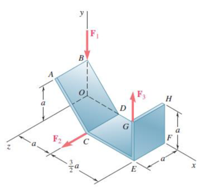
Chapter 3.4, Problem 3.134P
A piece of sheet metal is bent into the shape shown and is acted upon by three forces. If the forces have the same magnitude P, replace them with an equivalent wrench and determine (a) the magnitude and the direction of the resultant force R, (b) the pitch of the wrench, (c) the axis of the wrench.
Expert Solution & Answer
Want to see the full answer?
Check out a sample textbook solution
Students have asked these similar questions
3.4 Two forces F1 and F2 act on the screw eye. The resultant force Fr has a magnitude of 290 lb and the coordinate direction angles shown below. Solve for angle y, magnitude of F2, co-ordinate direction angles of a, b and y of F2.
The three forces shown are equivalent to a 50 kN upward force at A and a counterclockwise torque of 170 kN ⋅ m. Determine P and Q.
The figure shows a rigid body loaded with a system of forces. If the resultant of this system is a torque of 45 kN.m counterclockwise, determine: 1 The magnitude of P. 2 The magnitude of Q. 3 The magnitude of M. Measured in millimeters
Chapter 3 Solutions
Vector Mechanics for Engineers: Statics
Ch. 3.1 - A foot valve for a pneumatic system is hinged at...Ch. 3.1 - 3.2A foot valve for a pneumatic system is hinged...Ch. 3.1 - It is known that a vertical force of 200 lb is...Ch. 3.1 - A 300-N force is applied at A as shown. Determine...Ch. 3.1 - A 300-N force is applied at A as shown. Determine...Ch. 3.1 - An 8-lb force P is applied to a shift lever....Ch. 3.1 - Prob. 3.7PCh. 3.1 - An 11-lb force P is applied to a shift lever. The...Ch. 3.1 - Rod AB is held in place by the cord AC. Knowing...Ch. 3.1 - Rod AB is held in place by the cord AC. Knowing...
Ch. 3.1 - 3.11 and 3.12The tailgate of a car is supported by...Ch. 3.1 - 3.11 and 3.12The tailgate of a car is supported by...Ch. 3.1 - 3.13 and 3.14It is known that the connecting rod...Ch. 3.1 - 3.13 and 3.14It is known that the connecting rod...Ch. 3.1 - Form the vector product P1 P2 and use the result...Ch. 3.1 - The vectors P and Q are two adjacent sides of a...Ch. 3.1 - Prob. 3.17PCh. 3.1 - Prob. 3.18PCh. 3.1 - Prob. 3.19PCh. 3.1 - Prob. 3.20PCh. 3.1 - Before the trunk of a large tree is felled, cables...Ch. 3.1 - The 12-ft boom AB has a fixed end A. A steel cable...Ch. 3.1 - A 200-N force is applied as shown to the bracket...Ch. 3.1 - A force P of magnitude 200 N acts along the...Ch. 3.1 - A 6-ft-long fishing rod AB is securely anchored in...Ch. 3.1 - A precast concrete wall section is temporarily...Ch. 3.1 - In Prob. 3.22, determine the perpendicular...Ch. 3.1 - In Prob. 3.23, determine the perpendicular...Ch. 3.1 - In Prob. 3.24, determine the perpendicular...Ch. 3.1 - In Prob. 3.25, determine the perpendicular...Ch. 3.1 - In Prob. 3.25, determine the perpendicular...Ch. 3.1 - In Prob. 3.26, determine the perpendicular...Ch. 3.1 - In Prob. 3.26, determine the perpendicular...Ch. 3.1 - Determine the value of a that minimizes the...Ch. 3.2 - Given the vectors P = 2i + j + 2k, Q = 3i + 4j ...Ch. 3.2 - Form the scalar product B C and use the result...Ch. 3.2 - Three cables are attached to the top of the tower...Ch. 3.2 - Prob. 3.38PCh. 3.2 - Knowing that the tension in cable AC is 280 lb,...Ch. 3.2 - Knowing that the tension in cable AD is 180 lb,...Ch. 3.2 - Ropes AB and BC are two of the ropes used to...Ch. 3.2 - Ropes AB and BC are two of the ropes used to...Ch. 3.2 - The 20-in. tube AB can slide along a horizontal...Ch. 3.2 - Solve Prob. 3.43 for the position corresponding to...Ch. 3.2 - Determine the volume of the parallelepiped of Fig....Ch. 3.2 - Prob. 3.46PCh. 3.2 - A crane is oriented so that the end of the 25-m...Ch. 3.2 - 3.48The 25-m crane boom AO lies in the yz plane....Ch. 3.2 - To loosen a frozen valve, a force F with a...Ch. 3.2 - 3.50When a force F is applied to the handle of the...Ch. 3.2 - The 0.61 1.00-m lid ABCD of a storage bin is...Ch. 3.2 - Prob. 3.52PCh. 3.2 - A farmer uses cables and winch pullers B and E to...Ch. 3.2 - Solve Prob. 3.53 when the tension in cable AB is...Ch. 3.2 - A force P of magnitude 520 lb acts on the frame...Ch. 3.2 - 3.56A force P acts on the frame shown at point E....Ch. 3.2 - The frame ACD is hinged at A and D and is...Ch. 3.2 - In Prob. 3.57, determine the moment about the...Ch. 3.2 - The triangular plate ABC is supported by...Ch. 3.2 - 3.60The triangular plate ABC is supported by...Ch. 3.2 - Prob. 3.61PCh. 3.2 - Prob. 3.62PCh. 3.2 - Two forces F1 and F2 in space have the same...Ch. 3.2 - Prob. 3.64PCh. 3.2 - Prob. 3.65PCh. 3.2 - In Prob. 3.57, determine the perpendicular...Ch. 3.2 - In Prob. 3.58, determine the perpendicular...Ch. 3.2 - In Prob. 3.59, determine the perpendicular...Ch. 3.2 - In Prob. 3.60, determine the perpendicular...Ch. 3.3 - Two 80-N forces are applied as shown to the...Ch. 3.3 - Two parallel 60-N forces are applied as shown to...Ch. 3.3 - A multiple-drilling machine is used to drill...Ch. 3.3 - Four pegs of the same diameter are attached to a...Ch. 3.3 - A piece of plywood in which several holes are...Ch. 3.3 - The shafts of an angle drive are acted upon by the...Ch. 3.3 - Prob. 3.76PCh. 3.3 - 3.77If P = 20 lb in the figure, replace the three...Ch. 3.3 - The two couples shown are to be replaced with a...Ch. 3.3 - Solve part a of Prob. 3.78, assuming that two 15-N...Ch. 3.3 - Shafts A and B connect the gear box to the wheel...Ch. 3.3 - A 500-N force is applied to a bent plate as shown....Ch. 3.3 - A crane column supports a 16-kip load as shown....Ch. 3.3 - A dirigible is tethered by a cable attached to its...Ch. 3.3 - A 30-lb vertical force P is applied at A to the...Ch. 3.3 - A worker tries to move a rock by applying a 360-N...Ch. 3.3 - A worker tries to move a rock by applying a 360-N...Ch. 3.3 - The shearing forces exerted on the cross section...Ch. 3.3 - Knowing that = 60, replace the force and couple...Ch. 3.3 - Three control rods attached to a lever ABC exert...Ch. 3.3 - A rectangular plate is acted upon by the force and...Ch. 3.3 - While tapping a hole, a machinist applies the...Ch. 3.3 - A hexagonal plate is acted upon by the force P and...Ch. 3.3 - Replace the 250-kN force P with an equivalent...Ch. 3.3 - A 2.6-kip force is applied at point D of the...Ch. 3.3 - Replace the 150-N force with an equivalent...Ch. 3.3 - To keep a door closed, a wooden stick is wedged...Ch. 3.3 - A 46-lb force F and a 2120-lbin. couple M are...Ch. 3.3 - A 110-N force acting in a vertical plane parallel...Ch. 3.3 - The 12-ft boom AB has a fixed end A, and the...Ch. 3.3 - The jib crane shown is oriented so that its boom...Ch. 3.4 - 3.101A 4-m-long beam is subjected to a variety of...Ch. 3.4 - Prob. 3.102PCh. 3.4 - Determine the single equivalent force and the...Ch. 3.4 - Five separate force-couple systems act at the...Ch. 3.4 - The weights of two children sitting at ends A and...Ch. 3.4 - Three stage lights are mounted on a pipe as shown....Ch. 3.4 - A beam supports three loads of given magnitude and...Ch. 3.4 - A 6 12-in. plate is subjected to four loads as...Ch. 3.4 - Gear C is rigidly attached to arm AB. If the...Ch. 3.4 - To test the strength of a 625 500-mm suitcase,...Ch. 3.4 - Two cables exert forces of 90 kN each on a truss...Ch. 3.4 - Pulleys A and B are mounted on bracket CDEF. The...Ch. 3.4 - The roof of a building frame is subjected to the...Ch. 3.4 - A couple of magnitude M = 80 lbin. and the three...Ch. 3.4 - A couple M and the three forces shown are applied...Ch. 3.4 - A machine component is subjected to the forces and...Ch. 3.4 - Solve Prob. 3.116, assuming that P = 60 N.Ch. 3.4 - As follower AB rolls along the surface of member...Ch. 3.4 - A machine component is subjected to the forces...Ch. 3.4 - Two 150-mm-diameter pulleys are mounted on line...Ch. 3.4 - As an adjustable brace BC is used to bring a wall...Ch. 3.4 - In order to unscrew the tapped faucet A, a plumber...Ch. 3.4 - Assuming = 60 in Prob. 3.122, replace the two...Ch. 3.4 - Four forces are applied to the machine component...Ch. 3.4 - A blade held in a brace is used to tighten a screw...Ch. 3.4 - A mechanic uses a crowfoot wrench to loosen a bolt...Ch. 3.4 - Prob. 3.127PCh. 3.4 - Prob. 3.128PCh. 3.4 - Four signs are mounted on a frame spanning a...Ch. 3.4 - Prob. 3.130PCh. 3.4 - A concrete foundation mat of 5-m radius supports...Ch. 3.4 - Determine the magnitude and the point of...Ch. 3.4 - Prob. 3.133PCh. 3.4 - A piece of sheet metal is bent into the shape...Ch. 3.4 - Prob. 3.135PCh. 3.4 - Prob. 3.136PCh. 3.4 - Two bolts at A and B are tightened by applying the...Ch. 3.4 - Two bolts at A and B are tightened by applying the...Ch. 3.4 - Prob. 3.139PCh. 3.4 - A flagpole is guyed by three cables. If the...Ch. 3.4 - 3.141 and 3.142Determine whether the...Ch. 3.4 - 3.141 and 3.142Determine whether the...Ch. 3.4 - Replace the wrench shown with an equivalent system...Ch. 3.4 - Show that, in general, a wrench can be replaced...Ch. 3.4 - Show that a wrench can be replaced with two...Ch. 3.4 - Show that a wrench can be replaced with two...Ch. 3 - A 300-N force P is applied at point A of the bell...Ch. 3 - A winch puller AB is used to straighten a fence...Ch. 3 - A small boat hangs from two davits, one of which...Ch. 3 - Prob. 3.150RPCh. 3 - A single force P acts at C in a direction...Ch. 3 - The 23-in. vertical rod CD is welded to the...Ch. 3 - In a manufacturing operation, three holes are...Ch. 3 - A 260-lb force is applied at A to the rolled-steel...Ch. 3 - Prob. 3.155RPCh. 3 - A 77-N force F1 and a 31-Nm couple M1 are applied...Ch. 3 - Three horizontal forces are applied as shown to a...Ch. 3 - While using a pencil sharpener, a student applies...
Knowledge Booster


Learn more about
Need a deep-dive on the concept behind this application? Look no further. Learn more about this topic, mechanical-engineering and related others by exploring similar questions and additional content below.Similar questions
- Please solve with complete solutions and complete figures and enclose the final answer thank you. Given through the indicated points: A=280kN (12, 6, -4); B=520kN (-3, -4, 12); and C=270kN (6,-3,-6). Determine the resultant of the system of concurrent forces and the direction cosine of each of the axes having the following magnitudes, and passing through the origin.arrow_forwardThe pole OB is subjected to the 6004b force at B. Determine (a) the rectangular components of the force; and (b) the angles between the force vector and the coordinate axes.arrow_forward3. Concurrent forces of 150 lb is acting horizontally to the right, and a force of 350 lIb is acting upward to the right. If the resultant of these two forces is 444.41 Ib. a. Find the angle of the resultant with the positive-horizontal axis b. What is the angle of the 350 kN with the horizontal axis? 4. Given the sets of parallel forces shown: *Distances are in feet a. Determine the Support Reactions. b. Determine the location of the resultant force from the left support.arrow_forward
- Given the system of forces shown below, Determine the following:(a) Moment of the 361-lb force about Point ‘B’(b) Moment of the 1,414-lb force about Point ‘A’(c) Moment of the 224-lb force about Point ‘C’(d) Resultant of the force system (Magnitude and Direction)(e) Moment of all the forces about Point ‘O’(f) Locate the ‘x’ and ‘y’ intercept using point ‘O’ as the referencearrow_forwardQ (2): Knowing F2=420 N, F3=630 N. and the magnitude of the resultant force acting on the bracket is 650 N, directed along the positive u axis. Determine the magnitude of F and 50 its direction p.arrow_forward200 mm 75 mm A 20 N 15 A 20-N horizontal force is applied perpendicular to the handle of the socket wrench. Determine the magnitude of the moment created by this force about the y-axis.arrow_forward
- Three forces are acting on a bolt, namely, F, G, and H. If G is 324 N and H is 405 N, determine the following:a. the magnitude and direction of the components of force G when resolved along the u- and w-axes. b. the magnitude and direction of the resultant, denoted as P, of forces G and H c. the magnitude and direction of the minimum force F that will be added to P so that the resultant, R, is along the v-axisd. corresponding R *Note that the direction of force F in the figure is just assumed.arrow_forward3.1 Determine the resultant force acting on the hook.arrow_forwardQ4b. Force vectors F1 and F2 act on body Pwith the resultant force vector R. The resultant force R= 575 N and the angle between Rand the x-axis is of 320. If F1 = 275 N and the angle between F1 and the x-axis is 560, determine the angle between F2 and the x-axis. *Assume coplanar vector forces and give your answer in degrees to two decimal places. Body, P Answer: y F1 R F2arrow_forward
- The magnitude of the force P is 100 N. Determine the moments of P about (a) point O; and (b) point C.arrow_forwardC1.3 If a = 120°, B = 45°, y = 60°, and F = 400 lb, determine the magnitude and coordinate direction angles of the resultant force acting on the hook. F₁ = 600 lb B 30°arrow_forward4.5 • Forces F and F2 act at a point. The magnitude of F is 9.00 N, and its direction is 60.0° above the x-axis in the second quadrant. The magnitude of F, is 6.00 N, and its direction is 53.1° below the x-axis in the third quadrant. (a) What are the x- and y-components of the resultant force? (b) What is the magnitude of the resultant force? ng Section 4.3 Newton's Second Law 21 12:23 e to search 12°C Cloudy AG a 4 ENG 03/05/2022 DOLL insert delete home F11 end +1- prt sc F10 CE F3 F4 F5 F6 F7 F8 F9 F12 & num lock 3 %3D 8 9 R T Y P ome + IIarrow_forward
arrow_back_ios
SEE MORE QUESTIONS
arrow_forward_ios
Recommended textbooks for you
 International Edition---engineering Mechanics: St...Mechanical EngineeringISBN:9781305501607Author:Andrew Pytel And Jaan KiusalaasPublisher:CENGAGE L
International Edition---engineering Mechanics: St...
Mechanical Engineering
ISBN:9781305501607
Author:Andrew Pytel And Jaan Kiusalaas
Publisher:CENGAGE L
Column buckling; Author: Amber Book;https://www.youtube.com/watch?v=AvvaCi_Nn94;License: Standard Youtube License