
Concept explainers
Videos
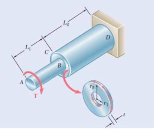
An annular plate of thickness t and modulus G is used to connect shaft AB of radius r1 to tube CD of radius r2. Knowing that a torque T is applied to end A of shaft AB and that end D of tube CD is fixed, (a) determine the magnitude and location of the maximum shearing stress in the annular plate, (b) show that the angle through which end B of the shah rotates with respect to end C of the tube is
Want to see the full answer?
Check out a sample textbook solution
Chapter 3 Solutions
Mechanics of Materials, 7th Edition


- 3.42 The angle of rotation of end A of the gear-and-shaft system shown must not exceed 4°. Knowing that the shafts are made of a steel for which Tall = 65 MPa and G = 77.2 GPa, determine the largest torque T that can be safely applied at end A. 30 mm B Tahap 60 mm 90 mm 30 mm 0.2 m 0.4 m 0.2 m 0.1 m 0.5 marrow_forwardPROBLEM 3.56 Two solid steel shafts are fitted with flanges that are then connected by bolts as shown. The bolts are slightly undersized and permit a 1.5° rotation of one flange with respect to the other before the flanges begin to rotate as a single unit. Knowing that G = 77 GPa, determine the maximum shearing stress in each shaft when a torque of T of magnitude 570 N m is applied to the flange indicated. The torque T is applied to flange C. 36 mm 30 mm T- 570 N- m B. 0.9 mm 0.6 mm TAB = 15.9 MPa TCD = 53 MPaarrow_forwardPROBLEM 3.56 Two solid steel shafts are fitted with flanges that are then connected by bolts as shown. The bolts are slightly undersized and permit a 1.5° rotation of one flange with respect to the other before the flanges begin to rotate as a single unit. Knowing that G = 77 GPa, determine the maximum shearing stress in each shaft when a torque of T of magnitude 570 N m is applied to the flange indicated. The torque T is applied to flange C. 36 mm 30 mm T-570 N m 0.9 mm 0.6 mm TAB 15.9 MPa TCD = 53 MPaarrow_forward
- Q2/ The torques shown, in Fig. 2, are exerted on pulleys A and B. Knowing that the shafts are solid and made of steel (G=77 GPa), determine the maximum shear stress (t) of shaft BC, and then find the total angle of twist (0) between A and C. Fig. 2 TA Ta 300 N-m 30 mm 400 N-m 46 mm 0.9 m 0.75 m c!arrow_forwardUsing Tall = 8.7 ksi and knowing that G= 5.6 × 10⁶ psi, determine for each of the cold-rolled yellow brass bars shown the largest torque T that can be applied and the corresponding angle of twist at end B. Refer to Table 3.1. B 2 in.- T 2 in. B 2.8 in. 1.4 in. 16 in. The torque for the brass bar (a) is The angle of twist for the brass bar (a) is The torque for the brass bar (b) is The angle of twist for the brass bar (b) is kip-in. kip-in. 0arrow_forwardA circular shaft AB consists of a 10-in.-long, 78-in.-diameter steel cylinder, in which a 5-in.-long, 58-in.-diameter cavity has been drilled from end B. The shaft is attached to fixed supports at both ends, and a 90 lb?ft torque is applied at its midsection . Determine the torque exerted on the shaft by each of the supports.arrow_forward
- The allowable shearing stress is 15 ksi in the 1.5-in.-diameter steel rod ABand 8 ksi in the 1.8-in.-diameter rod BC. Neglecting the effect of stress concentrations, determine the largest torque that can be applied at Aarrow_forwardTwo solid steel shafts are fitted with flanges that are then connected by bolts as shown. The bolts are slightly undersized and permit a 1.5° rotation of one flange with respect to the other before the flanges begin to rotate as a single unit. Knowing that G=77.2 GPa, determine the maximum shearing stress in each shaft when a torque T of magnitude 580 N-m is applied to the flange indicated. The torque T is applied to flange B. 30 mm 600 mm 36 mm T 900 mm The maximum shearing stress in shaft AB is The maximum shearing stress in shaft BC is MPa. MPa.arrow_forward3.36 The torques shown are exerted on pulleys B, C, and D. Knowing that the entire shaft is made of aluminum (G = 27 GPa), deter- mine the angle of twist between (a) C and B, (b) D and B. 30 mm 30 mm 400 N- m GG 36 mm 900 N- m 36 mm 500 N. m B "0.6 m E. 0.5 m D m 0.5 Fig. P3.36arrow_forward
- Two solid steel shafts are fitted with flanges that are then connected by bolts as shown. The bolts are slightly undersized and permit a 1.5° rotation of one flange with respect to the other before the flanges begin to rotate as a single unit. Knowing that G=77.2 GPa, determine the maximum shearing stress in each shaft when a torque T of magnitude 620 N-m is applied to the flange indicated. The torque T is applied to flange C. (Round the final answers to two decimal places.) 30 mm 600 mm 36 mm T-500 Nm 900 mm The maximum shearing stress in shaft AB is The maximum shearing stress in shaft CD is MPa. MPa.arrow_forwardThe aluminum rod AB (G = 27 GPa) is bonded to the brass rod BD (G = 39 GPa). Knowing that portion CD of the brass rod is hollow and has an inner diameter of 40 mm, determine the angle of twist at A. 60 mm TB = 1600 N-m 36 mm TA = 800 N-m 400 mm B 375 mm 250 mm Then, determine the maximum and minimum shearing stress in shaft CD.arrow_forwardTwo solid steel shafts are fitted with flanges that are then connected by bolts as shown. The bolts are slightly undersized and permit a 1.5° rotation of one flange with respect to the other before the flanges begin to rotate as a single unit. Knowing that G = 77 GPa, determine the maximum shearing stress in each shaft when a torque of T of magnitude 570 N m is applied to the flange indicated. The torque T is applied to flange C. 36 mm 30 mm T 570 N- m C B 0.9 mm 0.6 mmarrow_forward
 Elements Of ElectromagneticsMechanical EngineeringISBN:9780190698614Author:Sadiku, Matthew N. O.Publisher:Oxford University Press
 Mechanics of Materials (10th Edition)Mechanical EngineeringISBN:9780134319650Author:Russell C. HibbelerPublisher:PEARSON
 Thermodynamics: An Engineering ApproachMechanical EngineeringISBN:9781259822674Author:Yunus A. Cengel Dr., Michael A. BolesPublisher:McGraw-Hill Education
 Control Systems EngineeringMechanical EngineeringISBN:9781118170519Author:Norman S. NisePublisher:WILEY
 Mechanics of Materials (MindTap Course List)Mechanical EngineeringISBN:9781337093347Author:Barry J. Goodno, James M. GerePublisher:Cengage Learning
 Engineering Mechanics: StaticsMechanical EngineeringISBN:9781118807330Author:James L. Meriam, L. G. Kraige, J. N. BoltonPublisher:WILEY