
Physics for Scientists and Engineers: Foundations and Connections
1st Edition
ISBN: 9781133939146
Author: Katz, Debora M.
Publisher: Cengage Learning
expand_more
expand_more
format_list_bulleted
Videos
Textbook Question
Chapter 29, Problem 36PQ
A Each resistor shown in Figure P29.36 has resistance R. An ideal emf device (Ɛ) is connected to points a and b via two leads (not shown in the figure). Find an expression for the current through the emf device.
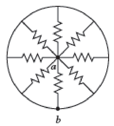
FIGURE P29.36
Expert Solution & Answer

Trending nowThis is a popular solution!

Students have asked these similar questions
A circuit consisting of 5 resistors is shown in the graph. Their resistances are R1 = 16 Ω, R2 = 35 Ω, R3 = 93 Ω, R4 = 36 Ω, and R5 = 32 Ω, and the emf of the battery is ε = 3.5 V. Suppose the internal resistance of the battery is zero.
a. Express the current I through R1 in terms of the emf ε and the equivalent resistance R.
b. Express the power P dissipated by R1 through I and R1.
c. Calculate the numerical value of I in A.
d. Calculate the numerical value of the power P in W.
a. As an assignment in a physics class, students are given three 120-Q resistors
to be connected in 4 possible ways. Draw each circuit and calculate the
equivalent resistance for each connection.
A 15 Ω resistor is connected to the terminals of a 1.5 V battery.a. Draw a graph showing the potential as a function of distance traveled through the circuit, starting from V = 0 V at the negative terminal of the battery.b. What is the current in the circuit?
Chapter 29 Solutions
Physics for Scientists and Engineers: Foundations and Connections
Ch. 29.1 - What are the SI units of ?Ch. 29.1 - Prob. 29.2CECh. 29.2 - Prob. 29.3CECh. 29.4 - Prob. 29.5CECh. 29.4 - Prob. 29.6CECh. 29.5 - Prob. 29.7CECh. 29 - Study the symbols in Table 29.2. Then, without...Ch. 29 - Prob. 2PQCh. 29 - Prob. 3PQCh. 29 - Suppose you need to measure the potential...
Ch. 29 - Prob. 5PQCh. 29 - Prob. 6PQCh. 29 - A real battery (modeled as an ideal emf device in...Ch. 29 - Prob. 8PQCh. 29 - Two circuits made up of identical ideal emf...Ch. 29 - Prob. 10PQCh. 29 - Prob. 11PQCh. 29 - Prob. 12PQCh. 29 - Eight real batteries, each with an emf of 5.00 V...Ch. 29 - Prob. 14PQCh. 29 - Prob. 15PQCh. 29 - Prob. 16PQCh. 29 - Prob. 17PQCh. 29 - Prob. 18PQCh. 29 - Prob. 19PQCh. 29 - An ideal emf device with emf is connected to two...Ch. 29 - Prob. 21PQCh. 29 - Prob. 22PQCh. 29 - Prob. 23PQCh. 29 - Prob. 24PQCh. 29 - Prob. 25PQCh. 29 - Prob. 26PQCh. 29 - Determine the currents through the resistors R2,...Ch. 29 - The emf devices in the circuits shown in Figure...Ch. 29 - Prob. 29PQCh. 29 - Prob. 30PQCh. 29 - Prob. 31PQCh. 29 - Prob. 32PQCh. 29 - Prob. 33PQCh. 29 - Prob. 34PQCh. 29 - A Figure P29.35 shows a combination of six...Ch. 29 - A Each resistor shown in Figure P29.36 has...Ch. 29 - Each resistor shown in Figure P29.36 has a...Ch. 29 - Prob. 38PQCh. 29 - Prob. 39PQCh. 29 - The emf in Figure P29.40 is 4.54 V. The...Ch. 29 - Figure P29.41 shows three resistors (R1 = 14.0 ,...Ch. 29 - Figure P29.42 shows five resistors and two...Ch. 29 - The emfs in Figure P29.43 are 1 = 6.00 V and 2 =...Ch. 29 - Prob. 44PQCh. 29 - Figure P29.45 shows five resistors connected...Ch. 29 - Figure P29.46 shows a circuit with a 12.0-V...Ch. 29 - Two ideal emf devices are connected to a set of...Ch. 29 - Two ideal emf devices are connected to a set of...Ch. 29 - Three resistors with resistances R1 = R/2 and R2 =...Ch. 29 - Prob. 51PQCh. 29 - Prob. 52PQCh. 29 - Prob. 53PQCh. 29 - Prob. 55PQCh. 29 - At time t = 0, an RC circuit consists of a 12.0-V...Ch. 29 - A 210.0- resistor and an initially uncharged...Ch. 29 - Prob. 58PQCh. 29 - A real battery with internal resistance 0.500 and...Ch. 29 - Figure P29.60 shows a simple RC circuit with a...Ch. 29 - Prob. 61PQCh. 29 - Prob. 62PQCh. 29 - Prob. 63PQCh. 29 - Ralph has three resistors, R1, R2, and R3,...Ch. 29 - Prob. 65PQCh. 29 - An ideal emf device is connected to a set of...Ch. 29 - Prob. 67PQCh. 29 - An ideal emf device (24.0 V) is connected to a set...Ch. 29 - Prob. 69PQCh. 29 - What is the equivalent resistance between points a...Ch. 29 - A capacitor with initial charge Q0 is connected...Ch. 29 - Prob. 73PQCh. 29 - Prob. 74PQCh. 29 - Prob. 75PQCh. 29 - Prob. 76PQCh. 29 - Figure P29.77 shows a circuit with two batteries...Ch. 29 - In the RC circuit shown in Figure P29.78, an ideal...Ch. 29 - Prob. 79PQCh. 29 - Calculate the equivalent resistance between points...Ch. 29 - In Figure P29.81, N real batteries, each with an...Ch. 29 - Prob. 82PQCh. 29 - Prob. 83PQCh. 29 - Prob. 84PQCh. 29 - Figure P29.84 shows a circuit that consists of two...Ch. 29 - Prob. 86PQCh. 29 - Prob. 87PQCh. 29 - Prob. 88PQCh. 29 - Prob. 89PQCh. 29 - Prob. 90PQCh. 29 - Prob. 91PQCh. 29 - Prob. 92PQCh. 29 - Prob. 93PQCh. 29 - Prob. 94PQCh. 29 - Prob. 95PQ
Knowledge Booster


Learn more about
Need a deep-dive on the concept behind this application? Look no further. Learn more about this topic, physics and related others by exploring similar questions and additional content below.Similar questions
- Each resistor shown in Figure P29.36 has a resistance of 100.0 . An ideal emf device (120.0 V) is connected to points a and b via two leads (not shown in the figure). Find the current that flows through the emf device.arrow_forwardThree resistors with resistances R1 = R/2 and R2 = R3 = R are connected as shown, and a potential difference of 225 V is applied across terminals a and b (Fig. P29.49). a. If the resistor R1 dissipates 75.0 W of power, what is the value of R? b. What is the total power supplied to the circuit by the emf? c. What is the potential difference across each of the three resistors?arrow_forwardAn ideal emf device (24.0 V) is connected to a set of resistors as shown in Figure P29.66. If R1 = 22.5 , R2 = 52.5 , R3 = 125 , and R4 = 75.0 , what is the voltage drop across each resistor?arrow_forward
- Two circuits made up of identical ideal emf devices ( = 1.67 V) and resistors (R = 35.9 ) are shown in Figure P29.8. What is the potential difference Vb Va a. for circuit 1 and b. for circuit 2? What is the current in the resistor c. in circuit 1 and d. in circuit 2?arrow_forwardFigure P29.42 shows five resistors and two batteries connected in a circuit. What are the currents I1, I2, and I3? FIGURE P29.42arrow_forwardFigure P29.41 shows three resistors (R1 = 14.0 , R2 = 8.00 , and R3 = 10.0 ) and two batteries connected in a circuit. a. What is the current in each of the resistors? b. How much power is delivered to each of the resistors?arrow_forward
- Eight real batteries, each with an emf of 5.00 V and an internal resistance of 0.200 , are connected end to end in a loop as in Figure P29.13. What is the terminal voltage across one of the batteries between points a and b?arrow_forwardIn Figure P29.81, N real batteries, each with an emf and internal resistance r, are connected in a closed ring. A resistor R can be connected across any two points of this ring, causing there to be n real batteries in one branch and N n resistors in the other branch. Find an expression for the current through the resistor R in this case.arrow_forwardTwo ideal emf devices are connected to a set of resistors as shown in Figure P29.47. If 1 = 6.00 V, R1 = 10.00 , R2 = 5.00 , R3 = 15.00 , R4 = 20.00 , and the current through R4 is 0.250 , what is the emf 2?arrow_forward
- An ideal emf device with emf is connected to two resistors in series. One of the resistors has resistance R1 and the other has unknown resistance R. If the current through the emf device is I, find an expression for the unknown resistance R in terms of the other quantities.arrow_forward(a) During surgery, a current as small as 20.0 ? applied directly to the heart may cause ventricular fibrillation. If the resistance of the exposed heart is 300 , what is the smallest voltage that poses this danger? (b) Does your answer imply that special electrical safety precautions are needed?arrow_forwardThe emf in Figure P29.40 is 4.54 V. The resistances are R1=13.0, R2=26.0, and R3=39.0 Find a. the current in each resistor, b. the power consumed by each resistor, and c. the power supplied by the emf device.arrow_forward
arrow_back_ios
SEE MORE QUESTIONS
arrow_forward_ios
Recommended textbooks for you
 Physics for Scientists and Engineers: Foundations...PhysicsISBN:9781133939146Author:Katz, Debora M.Publisher:Cengage Learning
 College PhysicsPhysicsISBN:9781938168000Author:Paul Peter Urone, Roger HinrichsPublisher:OpenStax College
Physics for Scientists and Engineers: Foundations...
Physics
ISBN:9781133939146
Author:Katz, Debora M.
Publisher:Cengage Learning
College Physics
Physics
ISBN:9781938168000
Author:Paul Peter Urone, Roger Hinrichs
Publisher:OpenStax College
DC Series circuits explained - The basics working principle; Author: The Engineering Mindset;https://www.youtube.com/watch?v=VV6tZ3Aqfuc;License: Standard YouTube License, CC-BY