In the circuit of Fig. E26.15 , each resistor represents a light bulb. Let R 1 , = R 2 = R 3 = R 4 = 4.50 Ω and ε = 9.00 V. (a) Find the current in each bulb, (b) Find the power dissipated in each bulb. Which bulb or bulbs glow the brightest? (c) Bulb R 4 is now removed from the circuit, leaving a break in the wire at its position. Now what is the current in each of the remaining bulbs R 1 , R 2 , and R 3 ? (d) With bulb R 4 removed, what is the power dissipated in each of the remaining bulbs? (c) Which light bulb(s) glow brighter as a result of removing R 4 ? Which bulb(s) glow less brightly? Discuss why there are different effects on different bulbs. Figure E26.15
In the circuit of Fig. E26.15 , each resistor represents a light bulb. Let R 1 , = R 2 = R 3 = R 4 = 4.50 Ω and ε = 9.00 V. (a) Find the current in each bulb, (b) Find the power dissipated in each bulb. Which bulb or bulbs glow the brightest? (c) Bulb R 4 is now removed from the circuit, leaving a break in the wire at its position. Now what is the current in each of the remaining bulbs R 1 , R 2 , and R 3 ? (d) With bulb R 4 removed, what is the power dissipated in each of the remaining bulbs? (c) Which light bulb(s) glow brighter as a result of removing R 4 ? Which bulb(s) glow less brightly? Discuss why there are different effects on different bulbs. Figure E26.15
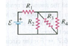
In the circuit of Fig. E26.15, each resistor represents a light bulb. Let R1, = R2 = R3 = R4 = 4.50 Ω and ε = 9.00 V. (a) Find the current in each bulb, (b) Find the power dissipated in each bulb. Which bulb or bulbs glow the brightest? (c) Bulb R4 is now removed from the circuit, leaving a break in the wire at its position. Now what is the current in each of the remaining bulbs R1, R2, and R3? (d) With bulb R4 removed, what is the power dissipated in each of the remaining bulbs? (c) Which light bulb(s) glow brighter as a result of removing R4? Which bulb(s) glow less brightly? Discuss why there are different effects on different bulbs.
In the circuit below, all four resistors are identical (R₁
R₁
R3
=
ww
R₂
R₂ = R3 = R4 = R) and the battery has a voltage of 5.12 V.
R4
(a) When the switch is placed in position 1, the measured current in the battery is 1.26 mA. What is the value of each resistor?
ΚΩ
(b) When the switch is placed in position 2, what is the current flowing out of the battery?
mA
(c) When the switch is open (neither in position 1 or position 2), what is the current flowing out of the battery?
mA
In the circuit pictured, the resistors have values of R =170 N, R2 = 62 N, and R3
= 130 Q, and the battery has an emf ɛ = 274 V.
(a) How much current ibatt, in amperes, goes through the battery?
(b) What is the current i2, in amperes, through resistor R2?
R
R3
Chapter 26 Solutions
University Physics with Modern Physics (14th Edition)
Need a deep-dive on the concept behind this application? Look no further. Learn more about this topic, physics and related others by exploring similar questions and additional content below.
How To Solve Any Resistors In Series and Parallel Combination Circuit Problems in Physics; Author: The Organic Chemistry Tutor;https://www.youtube.com/watch?v=eFlJy0cPbsY;License: Standard YouTube License, CC-BY


 Physics for Scientists and Engineers: Foundations...PhysicsISBN:9781133939146Author:Katz, Debora M.Publisher:Cengage Learning
 Principles of Physics: A Calculus-Based TextPhysicsISBN:9781133104261Author:Raymond A. Serway, John W. JewettPublisher:Cengage Learning
 College PhysicsPhysicsISBN:9781285737027Author:Raymond A. Serway, Chris VuillePublisher:Cengage Learning
 Physics for Scientists and Engineers, Technology ...PhysicsISBN:9781305116399Author:Raymond A. Serway, John W. JewettPublisher:Cengage Learning
 College PhysicsPhysicsISBN:9781305952300Author:Raymond A. Serway, Chris VuillePublisher:Cengage Learning