
Applied Statics and Strength of Materials (6th Edition)
6th Edition
ISBN: 9780133840544
Author: George F. Limbrunner, Craig D'Allaird, Leonard Spiegel
Publisher: PEARSON
expand_more
expand_more
format_list_bulleted
Concept explainers
Videos
Textbook Question
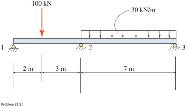
Chapter 21, Problem 21.21SP
For these problems, use any appropriate method of analysis. Unless noted otherwise, neglect the beam weight in all problems.
Expert Solution & Answer
Want to see the full answer?
Check out a sample textbook solution
Students have asked these similar questions
Draw the simplified free-body diagram and below it the shear and bending moment diagrams.
Show all necessary solutions. Let the analysis be from left to right. Determine the points of zero
shear (if any), their distance from point A, and the bending moments at these points. Indicate the
value of all the points, degree of all curves, and the maximum shear and maximum bending
moment of the beam.
Use the method of sections. Beam ABCD has a hanger
connected at B and is supported by a roller at A and a pin
at C.
100 N
L1
This is not your own property so
do not use it in any way as if it
were your own.
M
L1= 206 N/m
L2 = 30 N/m
L3 = 214 N/m
°
L4 = 89 N/m
M = 89 N-m
A
Simplified of the
you to repro
3. Any rexodus
ers have Exploratory Distance
x=
L2
1.5 m
Shear (N)
D
This is not your own property so
do not use it in any way as if it
were your own.
2.5m
Bending Moment (N-m)
L4
с
L3
Draw the shear and bending moment diagrams for beam loaded as shown
Refer to the beam shown and draw complete shear and bending moment diagrams. Show ordinates at key points and indicate magnitude of shear and moment. Neglect the beam weight.
Chapter 21 Solutions
Applied Statics and Strength of Materials (6th Edition)
Ch. 21 - Prob. 21.1PCh. 21 - Prob. 21.2PCh. 21 - Use the method of superposition to determine the...Ch. 21 - Draw complete shear and moment diagrams for the...Ch. 21 - Draw complete shear and moment diagrams for the...Ch. 21 - Draw complete shear and moment diagrams for the...Ch. 21 - Determine the reactions for the beam shown.Ch. 21 - Prob. 21.8PCh. 21 - 21.9 Select a southern pine timber beam () for the...Ch. 21 - For the continuous beams shown, find moments at...
Ch. 21 - For the continuous beams shown, find moments at...Ch. 21 - For the continuous beams shown, find moments at...Ch. 21 - Prob. 21.13SPCh. 21 - Prob. 21.14SPCh. 21 - Prob. 21.15SPCh. 21 - Prob. 21.16SPCh. 21 - Prob. 21.17SPCh. 21 - Prob. 21.18SPCh. 21 - Prob. 21.19SPCh. 21 - Prob. 21.20SPCh. 21 - For these problems, use any appropriate method of...Ch. 21 - For these problems, use any appropriate method of...Ch. 21 - Prob. 21.23SPCh. 21 - For these problems, use any appropriate method of...
Knowledge Booster


Learn more about
Need a deep-dive on the concept behind this application? Look no further. Learn more about this topic, mechanical-engineering and related others by exploring similar questions and additional content below.Similar questions
- For the beam and loading shown: 1- draw the axial, shearand bending moment diagrams 2- determine the maximum absolute values bending moment for each question 6 kN T-Im- 20 kN.m A B 10 KN 5 kN -1 m-1.5 m2 m- No. 1 4 C 2m D 10 kN H B 2 m No. 3 45 kN.m 20 A- C 1m 15 kN/m 3.0 m 6 m No. 2 62.5 KN Fis D E im 2 m No. 4 1.5 m 1.5 m B 20 Carrow_forwarddraw load, shear and bending moment diagrams for the following beam conditions. determine the maximum shear and bending moment magnitudes and locationsarrow_forwardDraw the shear and Bending moment diagram of each beam below using the equation method and area method. CHANGE 20 kN/m to 33 kN/marrow_forward
- Draw complete shear and bending moment diagrams. Show ordinates at key points and indicate magnitude of shear and moment. Neglect the beam weight.arrow_forwardUse the graphical method to construct the shear-force and bending-moment diagrams for the beam shown. Let a=4.0 ft, b=8.0 ft, c=4.0 ft, d=3.0 ft, w = 6.5 kips/ft and P = 45 kips. Construct the shear-force and bending-moment diagrams on paper and use the results to answer the questions in the subsequent parts of this GO exercise. A A a B a B W Answers: Ay = i b d For this loading, calculate the reaction forces Ay and Ey acting on the beam. Positive values for the reactions are indicated by the directions of the red arrows shown on the free-body diagram below. (Note: Since Ax = 0, it has been omitted from the free-body diagram.) W с b C C P C D P kips, Ey = d E i E X 'y x kips.arrow_forwardUse the graphical method to construct the shear-force and bending-moment diagrams for the beam shown. Let a=4.0 ft, b-8.0 ft, c-4.0 ft, d=3.0 ft, w = 6.5 kips/ft and P = 45 kips. Construct the shear-force and bending-moment diagrams on paper and use the results to answer the questions in the subsequent parts of this GO exercise. A a a B Part 2 b d For this loading, calculate the reaction forces Ay and Ey acting on the beam. Positive values for the reactions are indicated by the directions of the red arrows shown on the free-body diagram below. (Note: Since Ax = 0, it has been omitted from the free-body diagram.) Save for Later B W Answers: Ay = i 37.575 eTextbook and Media W AV=P₂ b C V₁ - V₁ = Sw(x) dx C C с D + D d kips, Ey= M₂ E i E ZA x Ey X Incorrect If your answer for part (a) or (e) is incorrect, recall that concentrated loads create discontinuities in the shear-force diagram. Refer to the table below (Construction Rules for Shear-Force and Bending-Moment Diagrams), Rule 1. At…arrow_forward
- Use the graphical method to construct the shear-force and bending-moment diagrams for the beam shown. Let a=3.5 ft, b=9.0 ft, c=4.0 ft, d=3.5 ft, w = 5.5 kips/ft and P = 45 kips. Construct the shear-force and bending-moment diagrams on paper and use the results to answer the questions in the subsequent parts of this GO exercise. For this loading, calculate the reaction forces Ay and Ey acting on the beam. Positive values for the reactions are indicated by the directions of the red arrows shown on the free-body diagram below. (Note: Since Ax = 0, it has been omitted from the free-body diagram.) Ay =___________ kips, Ey = __________ kips. Determine the shear force acting at each of the following locations:(a) x = 0+ ft (i.e., just to the right of support A)(b) x = 3.5 ft(c) x = 12.5 ft(d) x = 16.5– ft (i.e., just to the left of D)(e) x = 16.5+ ft (i.e., just to the right of D)(f) x = 20.0– ft (i.e., just to the left of support E) Answer: a to f ) V = ________ kips Use the graphical…arrow_forwardShear and moment in beams Draw the shear-force and bending-moment diagrams for the beam shown. Determine the maximum shear and maximum bending moment that occur in the span. provide detailed solutionarrow_forwardUse the graphical method to construct the shear-force and bending-moment diagrams for the beam shown. Let a=4.0 ft, b=8.0 ft, c=4.0 ft, d=3.0 ft, w = 6.5 kips/ft and P = 45 kips. Construct the shear-force and bending-moment diagrams on paper and use the results to answer the questions in the subsequent parts of this GO exercise. A a B a b For this loading, calculate the reaction forces Ay and Ey acting on the beam. Positive values for the reactions are indicated by the directions of the red arrows shown on the free-body diagram below. (Note: Since Ax = 0, it has been omitted from the free-body diagram.) W B W ÎÎÎÎÎÎ b C C d E d E X Ey Xarrow_forward
arrow_back_ios
SEE MORE QUESTIONS
arrow_forward_ios
Recommended textbooks for you
 Elements Of ElectromagneticsMechanical EngineeringISBN:9780190698614Author:Sadiku, Matthew N. O.Publisher:Oxford University Press
 Mechanics of Materials (10th Edition)Mechanical EngineeringISBN:9780134319650Author:Russell C. HibbelerPublisher:PEARSON
 Thermodynamics: An Engineering ApproachMechanical EngineeringISBN:9781259822674Author:Yunus A. Cengel Dr., Michael A. BolesPublisher:McGraw-Hill Education
 Control Systems EngineeringMechanical EngineeringISBN:9781118170519Author:Norman S. NisePublisher:WILEY
 Mechanics of Materials (MindTap Course List)Mechanical EngineeringISBN:9781337093347Author:Barry J. Goodno, James M. GerePublisher:Cengage Learning
 Engineering Mechanics: StaticsMechanical EngineeringISBN:9781118807330Author:James L. Meriam, L. G. Kraige, J. N. BoltonPublisher:WILEY
Elements Of Electromagnetics
Mechanical Engineering
ISBN:9780190698614
Author:Sadiku, Matthew N. O.
Publisher:Oxford University Press
Mechanics of Materials (10th Edition)
Mechanical Engineering
ISBN:9780134319650
Author:Russell C. Hibbeler
Publisher:PEARSON
Thermodynamics: An Engineering Approach
Mechanical Engineering
ISBN:9781259822674
Author:Yunus A. Cengel Dr., Michael A. Boles
Publisher:McGraw-Hill Education
Control Systems Engineering
Mechanical Engineering
ISBN:9781118170519
Author:Norman S. Nise
Publisher:WILEY
Mechanics of Materials (MindTap Course List)
Mechanical Engineering
ISBN:9781337093347
Author:Barry J. Goodno, James M. Gere
Publisher:Cengage Learning
Engineering Mechanics: Statics
Mechanical Engineering
ISBN:9781118807330
Author:James L. Meriam, L. G. Kraige, J. N. Bolton
Publisher:WILEY
Understanding Shear Force and Bending Moment Diagrams; Author: The Efficient Engineer;https://www.youtube.com/watch?v=C-FEVzI8oe8;License: Standard YouTube License, CC-BY
Bending Stress; Author: moodlemech;https://www.youtube.com/watch?v=9QIqewkE6xM;License: Standard Youtube License