Videos
Describe the behavior of the bulb in the two situations below.
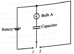
i. The switch is first moved to position 1. Describe the behavior of the bulb from just after the switch is closed until a long time later. Explain.
ii. The switch is now moved to position 2. Describe the behavior of the bulb from just after the switch is closed until a long time later. Explain your reasoning.
(i)
The behavior of the bulb from just after the switch is closed until a long time later in the situation when the switch is first moved to position
Explanation of Solution
Introduction:
Consider the circuit shown in Figure 1.
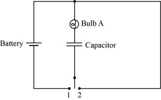
Figure 1
The brightness of the bulb depends upon the current flowing through that bulb. The bulb will be brighter if the flow of current through that bulb is high. In other words, more current passes through less resistance that mean if the resistance is less then bulb will appear brighter.
The circuit diagram when the switch is at position
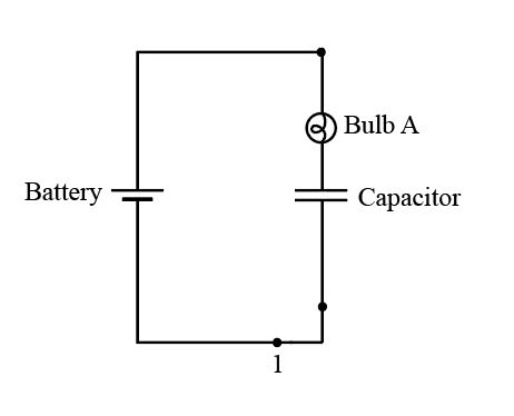
Figure 2
Initially, thecapacitor is short circuited and starts charging slowly. As thecurrent decays with respect to time, the bulb initially glows, but later it goes dimmer with time, and after a long time it stops glowing.
If it stops glowing, the capacitor comes in the open circuit condition and the current flow across it is zero.
Conclusion:
Therefore, the behavior of the bulb from just after the switch is closed until a long time later is described above.
(ii)
The behavior of the bulb from just after the switch is closed until a long time later in the situation when the switch is now moved to position
Explanation of Solution
Introduction:
The brightness of the bulb depends upon the current flowing through that bulb. The bulb will be brighter if the flow of current through that bulb is high. In other words, more current passes through less resistance that mean if the resistance is less then bulb will appear brighter.
The circuit diagram when the switch is at position
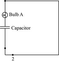
Figure 3
The capacitor voltage is equal to battery voltage at the initial stage.After this, capacitor startsdischarging and the currentdecays with time. So, blub glows bright initially, but thengoes dimmer with time, and after long timeit stops glowing.
If it stops glowing, the capacitor comes in the open circuit condition and the current flow across it is zero.
Conclusion:
Therefore, the behavior of the bulb from just after the switch is closed until a long time later is described above.
Want to see more full solutions like this?
Chapter 20 Solutions
Tutorials In Introductory Physics: Homework
Additional Science Textbook Solutions
Physics (5th Edition)
Physics for Scientists and Engineers: A Strategic Approach, Vol. 1 (Chs 1-21) (4th Edition)
College Physics (10th Edition)
Modern Physics
Essential University Physics: Volume 2 (3rd Edition)
Essential University Physics (3rd Edition)


- Consider the diagram at the right of a parallel circuit. Each light bulb has an identical resistance of R and the battery voltage is V. Use the labeled points on the diagram to answer the following questions. a. If the current at location A is I amperes, then the current at location B is ____ amperes. (Answer in terms of I.) b. If the current at location A is I amperes, then the current at location D is ____ amperes. (Answer in terms of I.) c. If the current at location A is I amperes, then the current at location L is ____ amperes. (Answer in terms of I.) d. If the voltage of the battery is doubled, then the current at location A would be ____ (two times, four times, one-half, one-fourth, etc.) the original value. e. If the voltage of the battery is doubled, then the current at location B would be ____ (two times, four times, one-half, one-fourth, etc.) the original value. f. If the voltage of the battery is doubled, then the current at location D would be ____ (two times, four times,…arrow_forwardConsider the diagram at the right of a series circuit. Each light bulb in the circuit has an identical resistance. Use the labeled points on the diagram to answer the following questions. Each question may have one, less than one, or more than one answer. a. The electric potential at point A is the same as the electric potential at point(s) ____. Include all that apply, if any apply. b. The electric potential at point C is the same as the electric potential at point(s) ____. Include all that apply, if any apply. c. The electric potential at point F is the same as the electric potential at point(s) ____. Include all that apply, if any apply. d. The electric potential at point I is the same as the electric potential at point(s) ____. Include all that apply, if any apply. e. The electric potential difference between points A and B is the same as the electric potential difference between points ___ and ____. Include all that apply, if any apply. f. The electric potential difference between…arrow_forwardPart D) Now apply the loop rule to loop 1 (the larger loop spanning the entire circuit). Sum the voltage changes across each circuit element around this loop going in the direction of the arrow. Express the voltage drops in terms of Vb, I1, I3, the given resistances, and any other given quantities. Answer=Σ(ΔV)=0= It is still saying incorrect because the correct answer does not depend on: I2, R2. Can you explain why that is and what the correct equation would be?arrow_forward
- Solve the following problem. Draw the schematic diagram for each scenario. B.2 Parallel If the resistors in problem B.1 were connected in parallel, solve for the: (a) equivalent resistance of the circuit (b) total current in the circuit (c) current through each resistor (d) voltage across each resistorarrow_forwardFor an ideal battery (r = 0 S2), closing the switch in (Figure 1) does not affect the brightness of bulb A. In practice, bulb A dims just a little when the switch closes. To see why, assume that the 1.50 V battery has an internal resistance r = 0.60 2 and that the resistance of a glowing bulb is R=4.00 2. Part A What is the current through bulb A when the switch is open? Express your answer with the appropriate units. • View Available Hint(s) HA IA, open = Value Units Submit Part B What is the current through bulb A after the switch has closed? Express your answer with the appropriate units. • View Available Hint(s) Figure 1 of 1 HA IA closed = Value Units Submit Part C By what percent does the current through A change when the switch is closed? Express your answer as a percentage. • View Available Hint(s) P Pearsonarrow_forwardA circuit contains a source of constant voltage V and two resistors connected in parallel, as shown in (Figure 1). Resistor 1 has resistance R1, and resistor 2 has resistance R2. Part C Now consider three resistors in parallel, with resistances R1, R2, and R3, as shown in (Figure 3). Again, draw a circuit diagram with a single equivalent resistor, with resistance R. What is the value of R? Figure 1 of 3 Express your answer in terms of R1, R2, and R3. V ΑΣΦ ? V R1 R2 R =arrow_forward
- Part I. Kirchhoff's Laws in 2 Loops. Find the necessary KVL/KCL equations to solve the problem. Compute for I1,I2, and I3 Resketch the circuit and label the current with the correct direction and values for each resistor. Note: For every wrong direction of a current, wrong value of current, or missing current for each resistor, there will be a deduction. 4. Find V1, V3, V5, and V7 5. Find P1, P3, P5 and P7Answer in GRESA Format.arrow_forwardA 24.0 V battery is wired in parallel with three resistors, R1 = 10.0 Ohms, R2 = 60.0 Ohms, and R3 = 150.0 Ohms. а.) circuit including proper symbols and labels. (Do not copy and paste an image from any other resource) Using either the computer drawing tools or a scanned hand written diagram, draw this b.) and label the current flow on your diagram. Find the equivalent resistance and total current running through the circuit. Show your work c.) Find the current flow and voltage drop through each resistor. Show your work and explain. werarrow_forwardThe emf phasor in (Figure 1) is shown at t = 12 ms. Assume Eo = 12 V. Part B Figure 1 of 1 What is the instantaneous value of the emf? Express your answer with the appropriate units. v View Available Hint(s) Hint 1. How to approach the problem Recall how the instantaneous value of emf depends on its magnitude and the direction of its phasor. 30° ol µA ? Phasor at t Value v V E =arrow_forward
- Constants In (Figure 1), the total resistance is 11.0 k, and the battery's emf is 24.0 V. The time constant is measured to be 18.0 us. Part B Calculate the time it takes for the voltage across the resistor to reach 14.0 V after the switch is closed. Express your answer to three significant figures and include the appropriate units. Figure <1 of 1 HẢ Value Units + Submit Request Answer Provide Feedhack 國arrow_forward1. The 300-µF capacitor in the figure on the right is initially charged to 100 V, the 1200-µF capacitor is uncharged, and the switches are both open. a. What is the maximum voltage to which you can charge the 1200-µF capacitor by the proper closing and opening of the two switches? b. How would you do it? Describe the sequence in which you would close and open switches and the times at which you would do so. The first switch is closed at t = 0. 300 µF: 5.3 H 1200 μFarrow_forward9 V B. The circuit at right is made from an ideal battery connected to 4 ideal resistors as shown. i. What is the total resistance of this circuit? Show your work. R4= 352 R1 = 152 R3 = 452 ii. Find the current through each of the 4 resistors. Show your work. R2= 752 iii. Rank the potential difference across the 4 resistors from greatest to least. Explain your reasoning. iv. If resistor R3 is cut out of the circuit, without replacing it with anything, will the current through resistor R2 increase, decrease, or stay the same? Explain your answer or show your work.arrow_forward
 College PhysicsPhysicsISBN:9781305952300Author:Raymond A. Serway, Chris VuillePublisher:Cengage Learning
 University Physics (14th Edition)PhysicsISBN:9780133969290Author:Hugh D. Young, Roger A. FreedmanPublisher:PEARSON
 Introduction To Quantum MechanicsPhysicsISBN:9781107189638Author:Griffiths, David J., Schroeter, Darrell F.Publisher:Cambridge University Press
 Physics for Scientists and EngineersPhysicsISBN:9781337553278Author:Raymond A. Serway, John W. JewettPublisher:Cengage Learning
 Lecture- Tutorials for Introductory AstronomyPhysicsISBN:9780321820464Author:Edward E. Prather, Tim P. Slater, Jeff P. Adams, Gina BrissendenPublisher:Addison-Wesley
 College Physics: A Strategic Approach (4th Editio...PhysicsISBN:9780134609034Author:Randall D. Knight (Professor Emeritus), Brian Jones, Stuart FieldPublisher:PEARSON