
Concept explainers
Videos
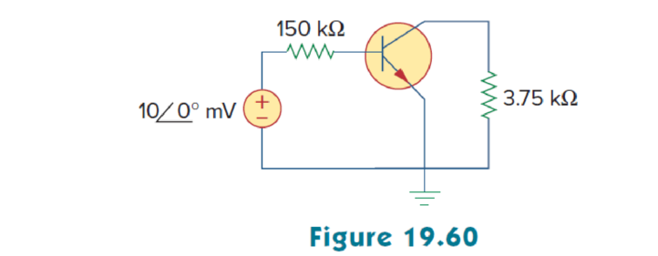
For the transistor amplifier of Fig. 19.60, find the voltage gain, current gain, input impedance, and output impedance. Assume that
Want to see the full answer?
Check out a sample textbook solution
Chapter 19 Solutions
Fundamentals of Electric Circuits
Additional Engineering Textbook Solutions
Electric Circuits. (11th Edition)
Microelectronics: Circuit Analysis and Design
Principles Of Electric Circuits
Principles and Applications of Electrical Engineering
Loose Leaf for Engineering Circuit Analysis Format: Loose-leaf
Introductory Circuit Analysis (13th Edition)


- 1. The transistors in Fig. 19-10 have the following parameter values: Q1: gml = 4 mS, raiz 00, and Q2: re2= 30 2, ro2 00. Find Avs. +12 Vo 310 ka I ka E Q: Q 100 k w o +12 V 500 e 40 kn 100 I Ma 270 n * ka 3 Vs Fig.19-10arrow_forwardSketch ir and vo for the network below for the input shown. 10 k2 10 V Si 5.3 V 7.3 V - -10 Varrow_forwardنقطة واحدة Q) The active instruments are .cheaper to manufacture T O Farrow_forward
- The ideal case for VSWR for matching condition is 2 0 1 infinity Oarrow_forwardQ/ An a.c bridge is in balance with the following constants : Arm AB , R=200 2 in series with C= 0.265 µF Arm AC , R2=300 2. Arm CD , Unknown. Arm BD, C3= 0.79 uF. The oscillator frequency is 1kHz , supply voltage =1volt between A and D points. Find: Zx and calculate its components (R, L or C).arrow_forwardAssume an idea converter showing below, what is the quality factor (Q) if the battery voltage (Vbatt) is 48V and the output is 24V. Please insert a numerical number and include the sign if the result is negative. V batt 2₁ DT, T 22 μΗ | ✈ D₁ 100 µF fs = 200 kHz V Load R=10ohmarrow_forward
- Vcc= 2.5 V 2 k2 600 2 2 k2 C3 VinoHHW Vout ㅇ 200 2 50Ω ERE1 C2 Consider the above circuit and answer the questions (observe Vout). 1) What happens if Re1 is changed to (compare with Re1 = 1kQ) а. 100 0 b. 2k O 2) What happens if the amplitude of the input signal is changed to (compare with Vin = 0.5 sin wt) a. 10 mV b. 2Varrow_forwardData must usually be reconverted to digital form for final consumption by the user Select one: O True O Falsearrow_forwardDetermine the V6arrow_forward
- For the following frequency response of an amplifier, the input to the amplifier is 1 mV, and the output is shown in the response below: Output Voltage (V) 0.16 0.14 0.12 0.1 0.08 0.06 0.04 0.02 0 100 Hz 1K Hz 10 KHz 100 KHz 1 MHz 10 MHz 1001arrow_forwardFor the cascaded system shown below determine the output voltage if vs = 1mV. Av₁ Auz R₂ + + 1kQ2 + Emitter-follower Zj = 10 ΚΩ Z=1292 Common-base Z₁ = 2622 Vo₁-Viz R₁ ' 8.2 ΚΩ 2=5.1 ΚΩ A 1 AL=240 =Zo 123mV O 134mV O -120mV -240mV ¹Z₁ = Z₁₁ 20₁ | Ziz 'Zo₂"arrow_forwardQ/ An a.c bridge is in balance with the following constants : Arm AB , R=200 Q in series with C= 0.265 µF. Arm AC , R,=300 2. Arm CD , Unknown. Arm BD, C3= 0.79 µF. The oscillator frequency is 1kHz , supply voltage =lvolt between A and D points. Find: Zx and calculate its components ( R, L or C).arrow_forward
 Introductory Circuit Analysis (13th Edition)Electrical EngineeringISBN:9780133923605Author:Robert L. BoylestadPublisher:PEARSON
 Delmar's Standard Textbook Of ElectricityElectrical EngineeringISBN:9781337900348Author:Stephen L. HermanPublisher:Cengage Learning
 Programmable Logic ControllersElectrical EngineeringISBN:9780073373843Author:Frank D. PetruzellaPublisher:McGraw-Hill Education
 Fundamentals of Electric CircuitsElectrical EngineeringISBN:9780078028229Author:Charles K Alexander, Matthew SadikuPublisher:McGraw-Hill Education
 Electric Circuits. (11th Edition)Electrical EngineeringISBN:9780134746968Author:James W. Nilsson, Susan RiedelPublisher:PEARSON
 Engineering ElectromagneticsElectrical EngineeringISBN:9780078028151Author:Hayt, William H. (william Hart), Jr, BUCK, John A.Publisher:Mcgraw-hill Education,