
Applied Statics and Strength of Materials (6th Edition)
6th Edition
ISBN: 9780133840544
Author: George F. Limbrunner, Craig D'Allaird, Leonard Spiegel
Publisher: PEARSON
expand_more
expand_more
format_list_bulleted
Videos
Textbook Question
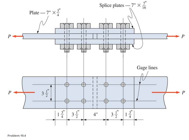
Chapter 19, Problem 19.4P
Compute the allowable tensile load for the double-shear butt joint shown. The plates are equivalent to
Expert Solution & Answer

Trending nowThis is a popular solution!

Students have asked these similar questions
A structural support for a machine will be subjected to a static tensile load of 16.0 kN.Specify suitable
dimensions for the cross section of the rod.
Design a cotter joint to support a axial load of122kN
kN . Carbon steel material selected which
has Tensile stress = 100MPa Compressive stress =150MPa; Shear stress=60MPa
Select the lightest WT4 shape to be used as a 20 ft long tension member to resist the of dead load, D=40 k, live load, L=60 k, snow load, PS=25 k, and earthquake, E=110 k. The connection is two lines of bolts through the flange with three 3/4-in ∅ bolts in each line spaced at 3 in on center. Use A992 Grade 50 steel. Neglect block shear.
Chapter 19 Solutions
Applied Statics and Strength of Materials (6th Edition)
Ch. 19 - Prob. 19.1PCh. 19 - Rework Problem 19.1 assuming a bearing-type...Ch. 19 - Rework Problem 19.1 assuming a bearing-type...Ch. 19 - Compute the allowable tensile load for the...Ch. 19 - Rework Problem 19.4 assuming a bearing-type...Ch. 19 - Rework Problem 19.4 assuming that the bolts are 34...Ch. 19 - Select the number and arrangement of 34 in....Ch. 19 - Calculate the allowable tensile load for the...Ch. 19 - In the connection shown, 14 in. side and end...Ch. 19 - Design the fillet welds parallel to the applied...
Ch. 19 - A fillet weld between two steel plates...Ch. 19 - Design an end connection using longitudinal welds...Ch. 19 - Calculate the allowable tensile load for the butt...Ch. 19 - Calculate the allowable tensile load for the lap...Ch. 19 - Calculate the allowable tensile load for the butt...Ch. 19 - Rework Problem 19.10 assuming that both plates are...Ch. 19 - Rework Problem 19.12 assuming that the angle is an...Ch. 19 - Two ASTM A36 steel plates, each 12 in. by 12 in. ,...Ch. 19 - Rework Problem 19.20 changing the fasteners to 34...Ch. 19 - Calculate the minimum main plate thickness for the...Ch. 19 - A roof truss tension member is made up of 2L6412...Ch. 19 - Rework Problem 19.23 changing the fasteners to six...Ch. 19 - Determine the allowable tensile load that can be...Ch. 19 - The welded connection shown is subjected to an...Ch. 19 - In Problem 19.26, use a 38 in. fillet weld, change...
Knowledge Booster


Learn more about
Need a deep-dive on the concept behind this application? Look no further. Learn more about this topic, mechanical-engineering and related others by exploring similar questions and additional content below.Similar questions
- A cylinder head stud has a diameter of 14mm at the bottom of the thread. If the maximum ten sile stress allowed in the material is 30MPa. Calculate the safe load the stud can carry.arrow_forwardQ2/ Calculate the maximum axial stress for a 40-ft joint of 11.75-in, 60 lbm/ft, J-55 casing with short threads coupling. Where the casing is subjected to 280000 lb, axial tension load in a portion of a directional wellbore with dogleg severity of 2"/50 ft. In case of: (1)Uniform contant between the casing and the borehole wall. (2)Assuming contant between borehole wall and the casing only at the couplings,andF n+ (3)Calculate the joint setrength of the API round thread couplings.(oult = 75000 psi, wall thickness 0.489-in, Pc= 2660 psi. o yb-952000 lb, Fj-649 000 lbf).arrow_forwardThe figure shows the handle super fast byke and its geometry with forces The cross section at the critical location is elliptical, with a major axis of 3 in and a minor axis of 1.5 in. For a load of 20 kip, estimate the stresses at the inner and outer surfaces of the critical section. 12-in R. 12-in R. 9 inarrow_forward
- An aluminum rod, made from alloy 6061-T6, is made in the form of a hollow square tube, 2.25 in outside with a wall thickness of 0.125 in. Its length is 16.0 in. It carries an axial compressive force of 12 600 lb. Compute the resulting design factor. Assume that the tube does not buckle.arrow_forwardA 5⁄8-inch-thick tension member is connected to two 1⁄4-inch splice plates, as shown in Figure The loads shown are service loads. A36 steel and 5⁄8-inchdiameter, Group A bolts will be used. If slip is permissible, how many bolts are required? Each bolt centerline shown represents a row of bolts in the direction of the width of the plates.arrow_forwardUse LRFD and design a 13-foot-long tension member and its connection for a service dead load of 8 kips and a service live load of 24 kips. No slip of the connection is permitted. The connection will be to a 3⁄8-inch-thick gusset plate, as shown in Figure . Use a single angle for the tension member. Use Group A bolts and A572 Grade 50 steel for both the tension member and the gusset plate.arrow_forward
- Select the lightest WT4 shape to be used as a 20 ft long tension member to resist the following service loads: dead load, D = 20 k, live load, L = 35 k, snow load, S = 25 k, and earthquake, E = 50 k. The connection is two lines of bolts through the flange with three 3/4-in Ø bolts in each line spaced at 3 in on center. Use A992 Grade 50 steel. Neglect block shear.arrow_forwardThe aircraft link is made from an A992 steel rod. (Figure 1) Figure 1 of 1 18 in.arrow_forwardDetermine the safe tensile load for bolts of (a) M 17 and (b) M 26. Assume that the bolts are not initially stressed and take the safe tensile stress as 305 MPaarrow_forward
- Two parts of a machine, both made from steel, are held together by 5 equally-spaced M6 x 1.0 grade 8.8 bolts that are uniformly tightened to provide a total initial clamping force of 23 kN in the members. Each bolt has a proof stress of 600 MPa, and a tensile area of 20.1 mm². The elasticities are such that the joint constant is 0.2. A uniform static tensile load of 12 kN is applied to the entire joint after it has been preloaded. What is the magnitude of the total clamping force in the joint after the application of the tensile load? Express your answer in units of kilonewtons.arrow_forwardQuestion 3 A typical Can dimensions are given as 63 mm in diameter, 120 mm in height and 0.1 mm thickness. These dimensions were measured on an aluminium beverage can which was carefully cut in half and measured the wall thickness and can diameter. Calculate the critical buckling load for the can and indicate if this is greater than or less than your weight. Does the can buckle? Assume the yield strength is 180 MPa and the elastic modulus is 69 GPa. A= 1= rg= The slenderness ratio is: 0J = x10^-9 m^4 The slenderness ratio is: Johnson equation )/( x10^-5 m^2 The buckling load P= m The buckling load An MPa N ) =arrow_forwardRigid bar ABC is supported by bronze rod (1) and aluminum rod (2), as shown. A concentrated load P is applied to the free end of aluminum rod (3). Bronze rod (1) has an elastic modulus of E₁ = 15,000 ksi and a diameter of d₁ = 0.40 in. Aluminum rod (2) has an elastic modulus of E₂ = 10,000 ksi and a diameter of d₂ = 0.70in. Aluminum rod (3) has a diameter of d3 = 1.00in. The yield strength of the bronze is 48 ksi and the yield strength of the aluminum is 40 ksi. Assume a = 2.5 ft, b = 1.5 ft, L₁= 6 ft, L₂= 8 ft, and L3 = 3 ft. (a) Determine the magnitude of load P that can safely be applied to the structure if a minimum factor of safety of 1.8 is required. (b) Determine the deflection of point D for the load determined in part (a). (c) The pin used at B has an ultimate shear strength of 57 ksi. If a factor of safety of 2.7 is required for this double shear pin connection, determine the minimum pin diameter that can be used at B. L₁ T A Bronze (1) B Aluminum (3) D Aluminum P b (2) L3 •…arrow_forward
arrow_back_ios
SEE MORE QUESTIONS
arrow_forward_ios
Recommended textbooks for you
 Elements Of ElectromagneticsMechanical EngineeringISBN:9780190698614Author:Sadiku, Matthew N. O.Publisher:Oxford University Press
 Mechanics of Materials (10th Edition)Mechanical EngineeringISBN:9780134319650Author:Russell C. HibbelerPublisher:PEARSON
 Thermodynamics: An Engineering ApproachMechanical EngineeringISBN:9781259822674Author:Yunus A. Cengel Dr., Michael A. BolesPublisher:McGraw-Hill Education
 Control Systems EngineeringMechanical EngineeringISBN:9781118170519Author:Norman S. NisePublisher:WILEY
 Mechanics of Materials (MindTap Course List)Mechanical EngineeringISBN:9781337093347Author:Barry J. Goodno, James M. GerePublisher:Cengage Learning
 Engineering Mechanics: StaticsMechanical EngineeringISBN:9781118807330Author:James L. Meriam, L. G. Kraige, J. N. BoltonPublisher:WILEY
Elements Of Electromagnetics
Mechanical Engineering
ISBN:9780190698614
Author:Sadiku, Matthew N. O.
Publisher:Oxford University Press
Mechanics of Materials (10th Edition)
Mechanical Engineering
ISBN:9780134319650
Author:Russell C. Hibbeler
Publisher:PEARSON
Thermodynamics: An Engineering Approach
Mechanical Engineering
ISBN:9781259822674
Author:Yunus A. Cengel Dr., Michael A. Boles
Publisher:McGraw-Hill Education
Control Systems Engineering
Mechanical Engineering
ISBN:9781118170519
Author:Norman S. Nise
Publisher:WILEY
Mechanics of Materials (MindTap Course List)
Mechanical Engineering
ISBN:9781337093347
Author:Barry J. Goodno, James M. Gere
Publisher:Cengage Learning
Engineering Mechanics: Statics
Mechanical Engineering
ISBN:9781118807330
Author:James L. Meriam, L. G. Kraige, J. N. Bolton
Publisher:WILEY
Differences between Temporary Joining and Permanent Joining.; Author: Academic Gain Tutorials;https://www.youtube.com/watch?v=PTr8QZhgXyg;License: Standard Youtube License