
Fundamentals of Electric Circuits
6th Edition
ISBN: 9780078028229
Author: Charles K Alexander, Matthew Sadiku
Publisher: McGraw-Hill Education
expand_more
expand_more
format_list_bulleted
Videos
Textbook Question
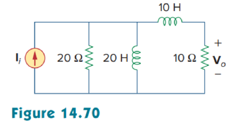
Chapter 14, Problem 3P
For the circuit shown in Fig. 14.70, find H(s) = V0(s)/Ii(s).
Expert Solution & Answer
Want to see the full answer?
Check out a sample textbook solution
Students have asked these similar questions
) Using the properties of F.T., Calculate the F.T. of the signal
sin(3nt) sin (5nt)
x(t) = 5
%3D
t2
Answer the following questions:
a)"
1 Given the output voltage signal Vo(s) below, find the output voltage in the time domain vo(t).
2
Vo(s)=
(s+2)(s+8)
b)
Discuss the application of Ohm's Law for a given R and C in series in both time and frequency domains.
Files
You can drag and drop files here to add them.
Next page
Q5)Find and draw the following signals
a)x(t)=5rect(2- t/4)
b)x(t)=4tri(6- 5t)
c)x(t) = e-2ltl Sin(5t)
d)for the signal below find and draw the following signals
ily(n) = }x(n) + }(-1)"x(n)
ii)y(n)=x(n)u(3-n)
-2 -1 0 12 3 4 5
Chapter 14 Solutions
Fundamentals of Electric Circuits
Ch. 14.2 - Obtain the transfer function VoVs of the RL...Ch. 14.2 - Prob. 2PPCh. 14.4 - Draw the Bode plots for the transfer function...Ch. 14.4 - Sketch the Bode plots for H()=50j(j+4)(j+10)2Ch. 14.4 - Construct the Bode plots for H(s)=10s(s2+80s+400)Ch. 14.4 - Obtain the transfer function H() corresponding to...Ch. 14.5 - A series-connected circuit has R = 4 and L = 25...Ch. 14.6 - A parallel resonant circuit has R = 100 k, L = 50...Ch. 14.6 - Calculate the resonant frequency of the circuit in...Ch. 14.7 - For the circuit in Fig. 14.40, obtain the transfer...
Ch. 14.7 - Design a band-pass filter of the form in Fig....Ch. 14.8 - Design a high-pass filter with a high-frequency...Ch. 14.8 - Design a notch filter based on Fig. 14.47 for 0 =...Ch. 14.9 - Prob. 14PPCh. 14.10 - Obtain the frequency response of the circuit in...Ch. 14.10 - Consider the network in Fig. 14.57. Use PSpice to...Ch. 14.12 - For an FM radio receiver, the incoming wave is in...Ch. 14.12 - Repeat Example 14.18 for band-pass filter BP6....Ch. 14.12 - If each speaker in Fig. 14.66 has an 8- resistance...Ch. 14 - Prob. 1RQCh. 14 - On the Bode magnitude plot, the slope of 1/5+j2...Ch. 14 - On the Bode phase plot for 0.5 50, the slope of...Ch. 14 - How much inductance is needed to resonate at 5 kHz...Ch. 14 - The difference between the half-power frequencies...Ch. 14 - Prob. 6RQCh. 14 - Prob. 7RQCh. 14 - Prob. 8RQCh. 14 - What kind of filter can be used to select a signal...Ch. 14 - A voltage source supplies a signal of constant...Ch. 14 - Find the transfer function Io/Ii of the RL circuit...Ch. 14 - Using Fig. 14.69, design a problem to help other...Ch. 14 - For the circuit shown in Fig. 14.70, find H(s) =...Ch. 14 - Find the transfer function H(s) = Vo/Vi of the...Ch. 14 - For the circuit shown in Fig. 14.72, find H(s) =...Ch. 14 - For the circuit shown in Fig. 14.73, find H(s) =...Ch. 14 - Calculate |H()| if HdB equals (a) 0.1 dB (b) 5 dB...Ch. 14 - Design a problem to help other students calculate...Ch. 14 - A ladder network has a voltage gain of...Ch. 14 - Design a problem to help other students better...Ch. 14 - Sketch the Bode plots for H()=0.2(10+j)j(2+j)Ch. 14 - A transfer function is given by...Ch. 14 - Construct the Bode plots for...Ch. 14 - Draw the Bode plots for H()=250(j+1)j(2+10j+25)Ch. 14 - Prob. 15PCh. 14 - Sketch Bode magnitude and phase plots for...Ch. 14 - Sketch the Bode plots for G(s)=s(s+2)2(s+1), s = jCh. 14 - A linear network has this transfer function...Ch. 14 - Sketch the asymptotic Bode plots of the magnitude...Ch. 14 - Design a more complex problem than given in Prob....Ch. 14 - Sketch the magnitude Bode plot for...Ch. 14 - Find the transfer function H() with the Bode...Ch. 14 - The Bode magnitude plot of H() is shown in Fig....Ch. 14 - The magnitude plot in Fig. 14.76 represents the...Ch. 14 - A series RLC network has R = 2 k, L = 40 mH, and C...Ch. 14 - Design a problem to help other students better...Ch. 14 - Design a series RLC resonant circuit with 0 = 40...Ch. 14 - Design a series RLC circuit with B = 20 rad/s and...Ch. 14 - Let vs = 20 cos(at) V in the circuit of Fig....Ch. 14 - A circuit consisting of a coil with inductance 10...Ch. 14 - Design a parallel resonant RLC circuit with 0 =...Ch. 14 - Design a problem to help other students better...Ch. 14 - A parallel resonant circuit with a bandwidth of 40...Ch. 14 - A parallel RLC circuit has R = 100 k, L = 100 mH,...Ch. 14 - A parallel RLC circuit has R = 10 k, L = 100 mH,...Ch. 14 - It is expected that a parallel RLC resonant...Ch. 14 - Rework Prob. 14.25 if the elements are connected...Ch. 14 - Find the resonant frequency of the circuit in Fig....Ch. 14 - For the tank circuit in Fig. 14.79, find the...Ch. 14 - Prob. 40PCh. 14 - Using Fig. 14.80, design a problem to help other...Ch. 14 - For the circuits in Fig. 14.81, find the resonant...Ch. 14 - Calculate the resonant frequency of each of the...Ch. 14 - For the circuit in Fig. 14.83, find: (a) the...Ch. 14 - For the circuit shown in Fig. 14.84. find 0, B,...Ch. 14 - For the network illustrated in Fig. 14.85, find...Ch. 14 - Prob. 47PCh. 14 - Find the transfer function Vo/Vs of the circuit in...Ch. 14 - Design a problem to help other students better...Ch. 14 - Determine what type of filter is in Fig. 14.87....Ch. 14 - Design an RL low-pass filter that uses a 40-mH...Ch. 14 - Design a problem to help other students better...Ch. 14 - Design a series RLC type band-pass filter with...Ch. 14 - Design a passive band-stop filter with 0 = 10...Ch. 14 - Determine the range of frequencies that will be...Ch. 14 - (a) Show that for a band-pass filter,...Ch. 14 - Determine the center frequency and bandwidth of...Ch. 14 - The circuit parameters for a series RLC band-stop...Ch. 14 - Find the bandwidth and center frequency of the...Ch. 14 - Obtain the transfer function of a high-pass filter...Ch. 14 - Find the transfer function for each of the active...Ch. 14 - The filter in Fig. 14.90(b) has a 3-dB cutoff...Ch. 14 - Design an active first-order high-pass filter with...Ch. 14 - Obtain the transfer function of the active filter...Ch. 14 - A high-pass filter is shown in Fig. 14.92. Show...Ch. 14 - A general first-order filter is shown in Fig....Ch. 14 - Design an active low-pass filter with dc gain of...Ch. 14 - Design a problem to help other students better...Ch. 14 - Design the filter in Fig. 14.94 to meet the...Ch. 14 - A second-order active filter known as a...Ch. 14 - Use magnitude and frequency scaling on the circuit...Ch. 14 - Design a problem to help other students better...Ch. 14 - Calculate the values of R, L, and C that will...Ch. 14 - Prob. 74PCh. 14 - In an RLC circuit, R = 20 , L = 4 H, and C = 1 F....Ch. 14 - Given a parallel RLC circuit with R = 5 k, L = 10...Ch. 14 - A series RLC circuit has R = 10 , 0 = 40 rad/s,...Ch. 14 - Redesign the circuit in Fig. 14.85 so that all...Ch. 14 - Refer to the network in Fig. 14.96. (a) Find...Ch. 14 - (a) For the circuit in Fig. 14.97, draw the new...Ch. 14 - The circuit shown in Fig. 14.98 has the impedance...Ch. 14 - Scale the low-pass active filter in Fig. 14.99 so...Ch. 14 - The op amp circuit in Fig. 14.100 is to be...Ch. 14 - Using PSpice or MultiSim, obtain the frequency...Ch. 14 - Use PSpice or MultiSim to obtain the magnitude and...Ch. 14 - Using Fig. 14.103, design a problem to help other...Ch. 14 - In the interval 0.1 f 100 Hz, plot the response...Ch. 14 - Use PSpice or MultiSim to generate the magnitude...Ch. 14 - Obtain the magnitude plot of the response Vo in...Ch. 14 - Obtain the frequency response of the circuit in...Ch. 14 - For the tank circuit of Fig. 14.79, obtain the...Ch. 14 - Using PSpice or MultiSim, plot the magnitude of...Ch. 14 - For the phase shifter circuit shown in Fig....Ch. 14 - For an emergency situation, an engineer needs to...Ch. 14 - A series-tuned antenna circuit consists of a...Ch. 14 - The crossover circuit in Fig. 14.108 is a low-pass...Ch. 14 - The crossover circuit in Fig. 14.109 is a...Ch. 14 - A certain electronic test circuit produced a...Ch. 14 - In an electronic device, a series circuit is...Ch. 14 - In a certain application, a simple RC low-pass...Ch. 14 - In an amplifier circuit, a simple RC high-pass...Ch. 14 - Practical RC filter design should allow for source...Ch. 14 - The RC circuit in Fig. 14.111 is used for a lead...Ch. 14 - A low-quality-factor, double-tuned band-pass...
Knowledge Booster


Learn more about
Need a deep-dive on the concept behind this application? Look no further. Learn more about this topic, electrical-engineering and related others by exploring similar questions and additional content below.Similar questions
- Find the Nyquist rate of the signal m(t) = sin 200nt Show your solution step by step. %3Darrow_forwardAns. Determine the response of the following system: x(n + 2) - 3 x(n + 1) + 2 x(n) = 8(n) %3D Assume that all the initial conditions are zero.arrow_forwardConsider the signal x(t) shown in the below figure. Find and sketch the a- signal x(-3t – 4). Show all steps in details. †x(t) -1arrow_forward
- b) Convert the following SOP expressions to the standard form. 1) AC+ AD + ACD, 2) ĀBD + CD + BCDarrow_forward8. De duce the trans fere function of the following active cimcuit, Here R,= 82 R2 F 10 52, R3=Rq=202 R3 Ri to V (t)arrow_forwardDetermine the range of K for stability in Figure below. R(s) E(s) K s(s+ 7)(s + 11) C(s)arrow_forward
- 3 R, ww R, ww out ROM For represented circuit sketch s-domain equivalent and compute the condition of oscillation and the frequency of oscillation. wwH ww wwarrow_forwardConsider the differential equation: What is the complementary function y? Ye = Ce* + c2xe* Ye = C1 sin 2x + c2 cos 2x %3D Ye = C1e-* + c2e* Ye = C1 sin x +c2 cosxarrow_forwardTranslation: Given that the Beta value is 80 and the IC current is 1mA as stated above, what is the value of the RC resistor? How to solve this could you explain step by step also what would change if the IC was 2mA ?arrow_forward
- Vout (s) of the circuit shown in figure Q4 Vin (s) Derive the transfer function · R4 R1 RS R2 C2 Vin(t) Vout (1) RS C1arrow_forwardConvert the following expression to sum-of-product(SOP) form (A+C)(AB+AC)arrow_forward4) F(s) = s-4s Ans. f(t) sinh(2r)-2t 1 5) F(s) = Ans. f(1) = (e" -1-21 – 21 )/ 8 -2.s 1 6) F(s): Ans. f(1) =1+t- cos(t)-sin(t)arrow_forward
arrow_back_ios
SEE MORE QUESTIONS
arrow_forward_ios
Recommended textbooks for you
 Introductory Circuit Analysis (13th Edition)Electrical EngineeringISBN:9780133923605Author:Robert L. BoylestadPublisher:PEARSON
 Delmar's Standard Textbook Of ElectricityElectrical EngineeringISBN:9781337900348Author:Stephen L. HermanPublisher:Cengage Learning
 Programmable Logic ControllersElectrical EngineeringISBN:9780073373843Author:Frank D. PetruzellaPublisher:McGraw-Hill Education
 Fundamentals of Electric CircuitsElectrical EngineeringISBN:9780078028229Author:Charles K Alexander, Matthew SadikuPublisher:McGraw-Hill Education
 Electric Circuits. (11th Edition)Electrical EngineeringISBN:9780134746968Author:James W. Nilsson, Susan RiedelPublisher:PEARSON
 Engineering ElectromagneticsElectrical EngineeringISBN:9780078028151Author:Hayt, William H. (william Hart), Jr, BUCK, John A.Publisher:Mcgraw-hill Education,
Introductory Circuit Analysis (13th Edition)
Electrical Engineering
ISBN:9780133923605
Author:Robert L. Boylestad
Publisher:PEARSON
Delmar's Standard Textbook Of Electricity
Electrical Engineering
ISBN:9781337900348
Author:Stephen L. Herman
Publisher:Cengage Learning
Programmable Logic Controllers
Electrical Engineering
ISBN:9780073373843
Author:Frank D. Petruzella
Publisher:McGraw-Hill Education
Fundamentals of Electric Circuits
Electrical Engineering
ISBN:9780078028229
Author:Charles K Alexander, Matthew Sadiku
Publisher:McGraw-Hill Education
Electric Circuits. (11th Edition)
Electrical Engineering
ISBN:9780134746968
Author:James W. Nilsson, Susan Riedel
Publisher:PEARSON
Engineering Electromagnetics
Electrical Engineering
ISBN:9780078028151
Author:Hayt, William H. (william Hart), Jr, BUCK, John A.
Publisher:Mcgraw-hill Education,
Why Use Bode Plots? | Understanding Bode Plots, Part 1; Author: MATLAB;https://www.youtube.com/watch?v=F6-EaZobHNk;License: Standard Youtube License