
University Physics Volume 2
18th Edition
ISBN: 9781938168161
Author: OpenStax
Publisher: OpenStax
expand_more
expand_more
format_list_bulleted
Videos
Textbook Question
Chapter 13, Problem 80CP
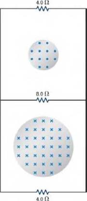
Two infinite solenoids cross the plane of the circuit as shown below. The radii of the solenoids are 0.10 and 020 m, respectively, and the current in each solenoid is changing such that
currents in die resistors of the circuit?
Expert Solution & Answer

Trending nowThis is a popular solution!

Students have asked these similar questions
In the circuit shown in the figure, Rị = 20.0 N, R2 = 30.0 N, R3 = 40.0 N, L = 15.0 H
%3D
and e = 100 V. What is the current i in units of ampere at t = 0.700 s after the switch
is closed.
R1
R3
R2
000
a. Consider the current configuration shown below. What is the magnitude of the cur-
rent in the wire marked with a question mark? Is the current entering or leaving the node?
2.20 A
1.40 A
1.50 A-
Current configurations for #1d
b. Consider the single loop circuit shown below. Calculate the current which flows in
the circuit. Is the current in the clockwise or the counterclockwise direction?
120 2
90 Ω 5.5 V 180 Ω
Single loop circuit configurations for #1b
A rectangular metal loop with 0.050Ω resistance is placed next to one wire of the RC circuit shown in the figure. The capacitor is charged to 20V with the polarity shown, then the switch is closed at t = 0s.
What is the direction of current in the loop for t > 0s?
What is the current in the loop at t = 5.0μs? Assume that only the circuit wire next to the loop is close enough to produce a significant magnetic field.
Chapter 13 Solutions
University Physics Volume 2
Ch. 13 - Chek sour Understanding A closely und coil has a...Ch. 13 - Check ‘sour Und.rtanding Find the dhectlon of the...Ch. 13 - Check Your UnderstAnding Verify the directions of...Ch. 13 - Check Your Understanding Shown below is a rod of...Ch. 13 - Check Your Understanding A rod of length 10cm...Ch. 13 - Check Your understanding Suppose that the coil of...Ch. 13 - Check Your Understanding What Is the magnitude of...Ch. 13 - Check your Understanding Themagneticfield shown...Ch. 13 - Check Your Understanding A long solenoid of...Ch. 13 - A stationary coil is in a magnetic field that is...
Ch. 13 - In Faraday’s experiments, what would be the...Ch. 13 - A copper ring and a wooden ring of the same...Ch. 13 - Discuss the factors determining the induced emf in...Ch. 13 - a. Does the induced emf in a circuit depend on the...Ch. 13 - How would changing the radius of loop D shown...Ch. 13 - Can there be an induced emf in a circuit at an...Ch. 13 - Does the induced emf always act to decrease the...Ch. 13 - How would you position a flat loop of wire in a...Ch. 13 - The normal to tt plane of a single-turn conducting...Ch. 13 - The circular conducting loops shown in the...Ch. 13 - The north pole of a mag’iet is moved toward a...Ch. 13 - The accompanying figure shows a conducting ring at...Ch. 13 - Show that and dm/dt have the same units.Ch. 13 - State the direction of the induced current for...Ch. 13 - A bar magnet falls under the influence of gravity...Ch. 13 - Around the geographic North Pole (or magnetic...Ch. 13 - A wire loop moves translationally (no rotation) in...Ch. 13 - Is the work required to accelerate a rod from rest...Ch. 13 - The copper sheet shown below is partially in a...Ch. 13 - A conducting sheet lies in a plane perpendicular...Ch. 13 - Electromagnetic braking can be achieved by...Ch. 13 - A coil is moved through a magnetic field as shown...Ch. 13 - A 50-turn coil has a diameter of 15 cm. The coil...Ch. 13 - Repeat your calculations of the preceding...Ch. 13 - A square loop whose sides are 6.0-cm long is made...Ch. 13 - The magnetic field through a circular loop of...Ch. 13 - The accompanying figure shows a single-turn...Ch. 13 - How would the answers to the preceding problem...Ch. 13 - A long solenoid with n= 10 turns per centimeter...Ch. 13 - A rectangular wire loop with length a and width b...Ch. 13 - The magnetic field perpendicular to a single sire...Ch. 13 - A single-turn circular loop of wire of radius 50...Ch. 13 - When a magnetic field is first turned on, t1 flux...Ch. 13 - The magnetic flux through the loop shown in the...Ch. 13 - Use Lenz’s law to determine tl direction of...Ch. 13 - An automobile with a radio antenna 1.0 m long...Ch. 13 - Prob. 38PCh. 13 - Suppose the magnetic field of the preceding...Ch. 13 - A coil of 1000 turns encloses an area of 25 cm2....Ch. 13 - In the circuit sho in the accompanying figure, the...Ch. 13 - The rod shown in the accompanying figure is moving...Ch. 13 - A 25-cm nod moves at 5.0 m/s in a plane...Ch. 13 - In the accompanying figure, the rails, connecting...Ch. 13 - The rod shown below moves to the right on...Ch. 13 - Shown below is a conducting rod that slides along...Ch. 13 - Calculate the induced electric field in a 50-tuni...Ch. 13 - The magnetic field through a circular loop of...Ch. 13 - The current I through a long solenoid with n trims...Ch. 13 - Calculate the electric field induced both inside...Ch. 13 - Prob. 51PCh. 13 - The magnetic field at all points within the...Ch. 13 - The current in a long solenoid of radius 3 cm is...Ch. 13 - The current in a long solenoid of radius 3 cm and...Ch. 13 - Design a current loop that, when rotated in a...Ch. 13 - A flat, square coil of 20 turns that has sides of...Ch. 13 - A 50-turn rectangular coil with dimensions...Ch. 13 - The square armature coil of an alternating current...Ch. 13 - A flip coil is a relatively simple device used to...Ch. 13 - The flip coil of the preceding problem has a...Ch. 13 - A 120-V, series-wound motor has a field resistance...Ch. 13 - A small series-wound dc motor is operated from a...Ch. 13 - Shown in the following figure is a long, straight...Ch. 13 - A metal bar of mass 500 g slides outward at a...Ch. 13 - A current is induced in a circular loop of radius...Ch. 13 - A metal bar of length 25 cm is placed...Ch. 13 - A coil with 50 turns and area 10cm2 is oriented...Ch. 13 - A 2-turn planer loop of flexible wire is placed...Ch. 13 - The conducting rod shown in the accompanying...Ch. 13 - A circular loop of wire of radius 10 cm is mounted...Ch. 13 - The magnetic field between the poles of a...Ch. 13 - A long solenoid of radius a with n turns per unit...Ch. 13 - A 120-V, series-wound dc motor draws 0.50 A from...Ch. 13 - The armature and field coils of a series-wound...Ch. 13 - A copper wire of Length I is fashioned into a...Ch. 13 - A 0.50-kg copper sheet drops through a uniform...Ch. 13 - A circular copper disk of radius 7.5 on rotates at...Ch. 13 - A short rod of length a moves with its velocity...Ch. 13 - A rectangular circuit containing a resistance R is...Ch. 13 - Two infinite solenoids cross the plane of the...Ch. 13 - An eight-turn coil is tightly wrapped around the...Ch. 13 - Shown below is a long rectangular loop of width w,...Ch. 13 - A square bar of mass m and resistance R is sliding...Ch. 13 - The accompanying figure shows a metal disk of...Ch. 13 - A long solenoid with 10 turns per centimeter is...Ch. 13 - The current in the long, straight wire shown in...Ch. 13 - A 500-turn coil with a 0.250m2 area is spun in...Ch. 13 - A circular loop of wire of radius 10 cm. is...Ch. 13 - A long solenoid of radius a with n turns per unit...Ch. 13 - A rectangular copper loop of mass 100 g and...Ch. 13 - A metal bar of mass m slides without friction over...Ch. 13 - A time-dependent uniform magnetic field of...
Additional Science Textbook Solutions
Find more solutions based on key concepts
96. A friend says that when twice as much works is done on a wagon, it will gain twice as much kinetic energy. ...
Conceptual Physical Science (6th Edition)
The circuits at right contain identical batteries and bulb. The boxes labeled X and Y representdifferent unknow...
Tutorials in Introductory Physics
4. A 4 N and a 10 N force act on an object. The moment arm of the 4 N force is 0.2 m. If the 10 N force produce...
College Physics (10th Edition)
10.83 You are designing a slide for a water park. In a sitting position, park guests slide a vertical distance ...
University Physics with Modern Physics (14th Edition)
(a) How much heat transfer occurs to the environment by an electrical power station that uses 1.251014J of heat...
College Physics
Show that only half the total energy drawn from a battery in charging an RC circuit ends up stored in the capac...
Essential University Physics: Volume 2 (3rd Edition)
Knowledge Booster


Learn more about
Need a deep-dive on the concept behind this application? Look no further. Learn more about this topic, physics and related others by exploring similar questions and additional content below.Similar questions
- Figure P29.60 shows a simple RC circuit with a 2.50-F capacitor, a 3.50-M resistor, a 9.00-V emf, and a switch. What are a. the charge on the capacitor, b. the current in the resistor, c. the rate at which the capacitor is storing energy, and d. the rate at which the battery is delivering energy exactly 7.50 s alter the switch is closed?arrow_forwardCalculate the current running through resistor R in the circuit shown in the figure. Give your answer in milliamps. Assume the following values for the circuit elements: 1.50 V Ra = 1.00 N Ri = 4.00 N Rc = 8.00 N 3.00 N Rd Re = 5.00 N Rf = 11.0 N Ra Rd Rb Rc Re Rfarrow_forwardThe figure below shows a capacitor, with capacitance C = 20.0 µF, and a resistor, with resistance R = 75.0 kN, con E = 21.0 V. The circuit has a switch, which is initially open. The circuit is a rectangular loop. The bottom side of the loop has an open switch S. The right side has a resistor R below a capacitor C. The left side has a battery labeled emf, oriented with the positive terminal above the negative terminal. (a) What is the circuit's time constant (in s)? (b) After the switch is closed for one time constant, how much charge (in C) is on the capacitor?arrow_forward
- R1 S R3. R2 4. Determine in the current in each resistor given that R1 = R2 = R3 = 1N, the capacitance C = 0.5 µF, and potential across the batter of E = 2V when the switch is closed at t = 0. Determine then after some time (t = 0) after the switch is closed the currents in each resistor.arrow_forwardS R 3. In the RC circuit shown in the figure, an ideal battery with emf E is connected to a capacitor C. The switch S is initially open and the capacitor is uncharged. At t = 0, the switch is closed. R C a) What is the current through c – d at t = 0? d b) What is the current through c – d as t goes to infinity? e c) What is the current through b – e as t goes to infinity? + 3.arrow_forwardAn initially uncharged capacitor is connected as shown. If the switch is closed at t0, the time it takes the capacitor to reach BO% of its final voltage is T. f the time constant of the circuit is t, determine T/r. R ww O16 22 5.0 3.0 1.9arrow_forward
- A solenoid has a radius of 3.5 cm, 160 turns and a length of 1.2 m. Take the solenoid to have negligible (zero) resistance. The terminals of the solenoid are connected across a 15 Ω resistor at time zero and the circuit is given an initial current of 55 mA. a) How long will it take for the current to drop to 12mA? b) At time zero, just after the current in the circuit is initiated, what is the energy stored in the solenoid and what is the voltage across the solenoid?arrow_forwardThe switch S, is closed for a long time in the circuit shown. Then, S, is opened and Sz is closed simultaneously. What is the maximum charge that can be stored in E the capacitor? ɛ = 30 V, L = 4 mH, R = 5 0, C = 6 µF LE R None of them 0.65 mC 0.35 mC 0.93 C 0.93 mC 0.65 C 0.35 Carrow_forwardThe switch S, is closed for a long time in the circuit shown. Then, S, is opened and Sz is closed simultaneously. What is the maximum charge that can be stored in E the capacitor? ɛ = 30 V, L = 4 mH, R = 5 Q, C = 6 µF L R None of them 0.65 mC 0.35 mC 0.93 C 0.65 C 0.35 C 0.93 mCarrow_forward
- For the given circuit switch is opened at t=0 after being closed for a long time. R=40 Ohm, C=25mF, L=10H is (1 5 V 1) If i,(t) = 10 u(t)A a. iz(0") =? b. i(t) =? 2) If i,(t) = e-3t u(t)A a. i,(0) =? b. i(t) =?arrow_forwardFor the circuit shown below, Ɛ = 32 V, R, = 27 N, R, = 54 N, R3 = 81 N, and L = 4.0 mH. Find the values of I, and I, (in A) at the following times. R1 R3 1/2 R2 (a) immediately after switch S is closed I, = A I2 A (b) a long time after S is closed I, A I2 A (c) immediately after S is reopened (Assume the circuit has reached a steady state before S is reopened.) I = A I2 A = (d) a long time after S is reopened A I, = A 0000arrow_forwardConsider the circuit shown in the figure below, where L = 5.45 mH and R2 = 500 Ω. The switch S can be positioned at either a or b. A circuit contains a battery, a switch, an inductor, and two resistors. The battery is labeled 24.0 V and is on the left side of the circuit. The positive terminal is above the negative terminal. The circuit starts at the positive terminal and extends directly up, then directly to the right where it reaches the switch at a point labeled a. The switch is labeled S and allows the circuit to alternate between two paths. The first path starts at the positive terminal of the battery, goes up and then to the right through the switch from the point labeled a to a point without a label, goes to the right through the inductor labeled L at the top of the circuit, goes down through the resistors labeled R1 and R2 placed in parallel with each other on the right side of the circuit, goes to the left through a wire running directly from the right side of the circuit…arrow_forward
arrow_back_ios
SEE MORE QUESTIONS
arrow_forward_ios
Recommended textbooks for you
 Physics for Scientists and Engineers: Foundations...PhysicsISBN:9781133939146Author:Katz, Debora M.Publisher:Cengage Learning
Physics for Scientists and Engineers: Foundations...
Physics
ISBN:9781133939146
Author:Katz, Debora M.
Publisher:Cengage Learning
What is Electromagnetic Induction? | Faraday's Laws and Lenz Law | iKen | iKen Edu | iKen App; Author: Iken Edu;https://www.youtube.com/watch?v=3HyORmBip-w;License: Standard YouTube License, CC-BY