
Concept explainers
Videos
The hub diameter and projection for the gear of Prob. 13–51 are 100 and 37.5 mm, respectively. The face width of the gear is 50 mm. Locate bearings C and D on opposite sides, spacing C 10 mm from the gear on the hidden face (see figure) and D 10 mm from the hub face. Choose one as the thrust bearing, so that the axial load in the shaft is in compression. Find the output torque and the magnitudes and directions of the forces exerted by the bearings on the gearshaft.
The output torque.
The force exerted by the bearing
The force by the bearing
Answer to Problem 52P
The output torque is
The force exerted by the bearing
The force by the bearing
Explanation of Solution
The figure below shows the forces acting at the centre of the gear
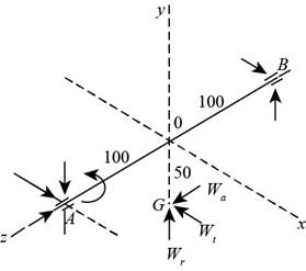
Figure-(1)
The tangential load on the centre of the gear is
The figure below shows the forces on the bearing
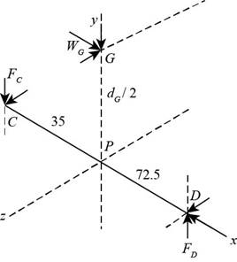
Figure-(2)
Write the expression for the linear velocity of the worm.
Here, the pitch diameter of the worm is
Write the expression for the tangential load on the gear.
Here, the power is
Write the expression for lead.
Here, the number of threads on worm is
Write the expression for the lead angle.
Write the expression for the force exerted by the by the gear on the worm.
Here, the normal pressure angle is
Write the expression for the sliding velocity.
Write the expression for the load in the y direction.
Write the expression for the load in the z direction.
Write the expression for vector form of the force against the worm.
The force on the gear will be equal but opposite to the force against the worm.
Write the expression for vector form of the force against the gear.
Write the diameter of the gear.
Here, the number of teeth on the gear is
The axial pitch and the transverse pitch is same hence
Write the position vector of
Here, the distance between the points
Write the position vector of
Here, the distance between the points
Write the moment equation at
Here, the force vector at
Write the expression for the force vector at
Here, the force in x-direction is
Write the force balance equation for the bearing
Conclusion:
Substitute
Substitute
Substitute
Substitute
Substitute
Convert the units of sliding velocity from
Refer to Figure 13-42 “Representative values of the coefficient of friction for worm gearing.” to obtain the friction coefficient as 0.043 with respect to sliding velocity as
Substitute
Substitute
Substitute
Substitute
Substitute
Substitute
Substitute
Substitute
Substitute
Solve Equation (XVII) for
Thus, the output torque is
Solve Equation (XVII) for
Solve Equation (XVII) for
Substitute
Thus, the force exerted by the bearing
Substitute
Thus, the force by the bearing
Want to see more full solutions like this?
Chapter 13 Solutions
Shigley's Mechanical Engineering Design (McGraw-Hill Series in Mechanical Engineering)


- A gear reduction unit uses the countershaft shown in the figure. Gear A receives power from another gear with the transmitted force FA applied at the 20 pressure angle as shown. The power is transmitted through the shaft and delivered through gear B through a transmitted force Fg at the pressure angle shown. For the steel countershaft shown below, assume the bearings have a maximum slope specification of 0.064" for good bearing life. Does the dia shown below meet the requirement? if not determine a suitable shaft diameter. 1.25-in da Gear A F₁-300- Gear B Sindia The minimum shaft diameter is in.arrow_forwardIn the figure below, a motor with power 150kw and speed of 2500 rpm is connected to shaft 1(by coupling) in a clockwise direction. Shaft 2 is connected to shaft 1 by gears 1 and 2. If 30% of the power is consumed by the gear3 and 9% by the pulley and 61% by the sprocket, draw torque diagrams for both shafts. • Lengths: AB=90mm/BC=GH=50mm/CD3HI=60mm/DE=IJ=80mm 13 Gear3 E Gear2 14 15 16 Motor shafth 2. 17 Bearing Shaft1 Gear1 sprocketarrow_forwardThe motor in the figure applies a torsion (torque) of 50 Nm to the shaft AB. This torque is transferred to the CD shaft with the help of gears at points E and F. Bearings at B, C and D points provide free rotation to the shafts. Calculate the torque T' on the CD Shaft? 50 mm 30 mm B 35 mm T 125 mmarrow_forward
- For the gear mechanism in the figure: P1 = 4 kW, η1 = 1000 rpm, z1 = 18, z2 = 36, z3 = 54, z4 = 108, z1 is the driving gear. Total efficiency values for each stage; Since η12 = η34 = 0.96; Find the output torque and speed of gear z4.arrow_forwardThe problem is stated below. However, change the position of torque to point C from point D. What is the effect of variation of torque placement in shaft CB?arrow_forwarda) A line shaft as shown in Figure Q is driven using a motor placed vertically below it. The pulley on the line shaft is 1.6 m in diameter and has belt tensions 7.5 kN and 2.4 kN on the tight side and slack side of the belt respectively. Both tensions may be assumed to be vertical and the weight of the pulley is negligible. If the pulley is overhang from the shaft, the distance of the centre line of the pulley from the centre line of the bearing being 500 mm.6.Figure Q(i) Predict using distortion energy theory, the appropriate diameter of the shaft that failure will not occur if the yield strength, Sy = 370 Mpa and factor of safety is 2.5. (ii) Assuming the maximum allowable shear stress of 42 MPa, find its diameter using maximum shear stress theory. (iii) Comparing the diameters in (i) and (iii) above, which of them would you have used to design your shaft and why?arrow_forward
- A solid constant-diameter circular shaft is subjected to the torques of TA = 480 lb-ft, TB = 1060 lb-ft, Tc= 860 lb-ft, and Tp = 280 lb-ft, acting in the directions shown. The bearings shown allow the shaft to turn freely. (a) Plot a torque diagram showing the internal torque in segments (1), (2), and (3) of the shaft. Use the sign convention presented in %D Section 6.6. (b) If the allowable shear stress in the shaft is 5800 psi, what is the minimum acceptable diameter for the shaft? TB TA Tc (1) Tp (3) В C D Answer: (a) T1 = Ib-ft T2 = Ib-ft T3 = Ib-ft (b) d = in.arrow_forwardPLEASE ANSWER ?? ?Part 1 Calculate the polar moments of inertia in segments (1) and (2). Please Answer: J₁ = in.⁴ J₂= in. ⁴ ?Part 2 Calculate the internal torques T1 and T2 in shaft segments (1) and (2), respectively. On paper, prepare an internal torque diagram for the compound shaft that shows these internal torques. Use the sign convention presented in Section 6-6. Please Answer: T₁ = Ib-ft, T₂= Ib-ft. ?Part 3 Calculate the maximum shear stress in each shaft segment. On paper, prepare a diagram that shows the maximum shear stress in segments (1) and (2) of the shaft. Use the sign convention presented in Section 6-6. Please Answer: τ₁ = psi, τ₂ = psi ?Part 4 Determine the rotation angle of B with respect to the support at A. Please Answer: φB= rad. ?Part 5 Determine the rotation angle of C with respect to the support at A. Please Answer: φC= rad. Thank you so much in advancearrow_forwardA conveyor is used to drive the inertial load of 0.02 kg m² in the required speed range with a brushless DC motor and a gearhead having reduction ratio of 15:1 as shown in the figure below. The belt speed is V=1 m/s and the roller diameter is D=0.1 m. Choose the correct statement. Load Motor Right Angle Gearhead O The moment of inertia of the load referred to the motor shaft is 0.00133 kg m² O The moment of inertia of the load referred to the motor shaft is 0.0133 kg m² O The rotation speed of the motor shaft is 1665 RPM O The rotation speed of the gear shaft is 100 RPM O The rotation speed of the motor shaft is 2865 RPM.arrow_forward
- A solid constant-diameter circular shaft is subjected to torques TA = 420 lb- ft, TB = 1,040 lb- ft, TC = 850 lb-ft, andTD = 230 lb-ft, acting in the directions shown in the figure. The bearings shown allow the shaft to turn freely. (a) Plot a torque diagram showing the internal torque in segments (1), (2), and (3) of the shaft. Use the right-hand rule. (b) If the allowable shear stress in the shaft is 6,000 psi, what is the minimum acceptable diameter for the shaft?arrow_forwardThree spur gear are arranged shown in the figure. Pinion A rotates for about 500 rpm. The three gears have a diametral pitch of 5. Number of teath and angle is shown in the figure. Determine the torque that each shaft is required to transmit and the resultant force on the shaft carrying the gear B. Draw the FBD of the figure.arrow_forwardFind βW for the torque- angle diagram shown. The enclosed areas are , A1 = 400 J , A2 = 800 J , A3 = 550 J and A4 = 150 J Find the moment of inertia for a flywheel which will keep the speed within the range 410 to 416 rev/min. and find the mass of a suitable flywheel with a radius of gyration of 0.5 m.arrow_forward
 Elements Of ElectromagneticsMechanical EngineeringISBN:9780190698614Author:Sadiku, Matthew N. O.Publisher:Oxford University Press
 Mechanics of Materials (10th Edition)Mechanical EngineeringISBN:9780134319650Author:Russell C. HibbelerPublisher:PEARSON
 Thermodynamics: An Engineering ApproachMechanical EngineeringISBN:9781259822674Author:Yunus A. Cengel Dr., Michael A. BolesPublisher:McGraw-Hill Education
 Control Systems EngineeringMechanical EngineeringISBN:9781118170519Author:Norman S. NisePublisher:WILEY
 Mechanics of Materials (MindTap Course List)Mechanical EngineeringISBN:9781337093347Author:Barry J. Goodno, James M. GerePublisher:Cengage Learning
 Engineering Mechanics: StaticsMechanical EngineeringISBN:9781118807330Author:James L. Meriam, L. G. Kraige, J. N. BoltonPublisher:WILEY