
Fundamentals of Electric Circuits
6th Edition
ISBN: 9780078028229
Author: Charles K Alexander, Matthew Sadiku
Publisher: McGraw-Hill Education
expand_more
expand_more
format_list_bulleted
Concept explainers
Videos
Textbook Question
Chapter 12, Problem 84CP
Figure 12.76 displays a three-phase delta-connected motor load which is connected to a line voltage of 440 V and draws 4 kVA at a power factor of 72 percent lagging. In addition, a single 1.8 kVAR capacitor is connected between lines a and b, while a 800-W lighting load is connected between line c and neutral. Assuming the abc sequence and taking Van = Vp
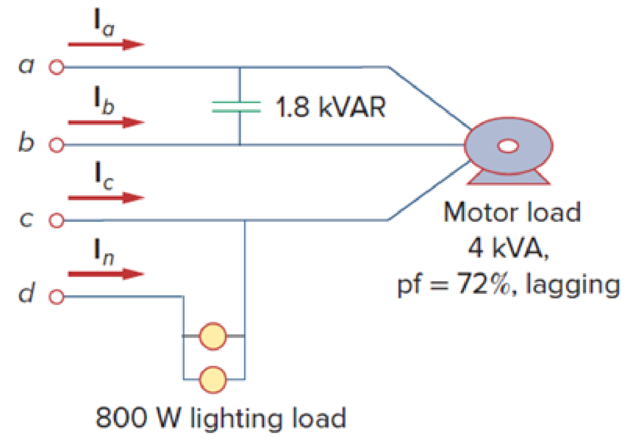
Figure 12.76
Expert Solution & Answer
Want to see the full answer?
Check out a sample textbook solution
Students have asked these similar questions
Three Impedances each of (8 - j18) are
connected in mesh across a three-phase
410V ac supply. Determine the phase
current, line current, active power, reactive
power drawn from supply. Also draw the
Phasor diagram for the mesh connection
and marks the Line current ,phase current
line voltage and phase angle between
phase current and pahse voltage. I
phase current (Ip)
Line current
real power
reactive power
1. What is the main direct cause of reactive power in AC system?
A. Resistance of transmission lines
B. Inductance and capacitance in the loads
C. Ideal transformer connected in the system
D. Power produced by generator
2. "Reactive power in a system is dissipated generally as thermal energy?"
A. TRUE
B. FALSE
3. Which of the following statements are correct for three phase circuit:
A. Sum of all the three phase currents is zero in unbalanced network
B. Total power transfer to load is constant with time
C. Neutral conductor is same size in terms of material used as in single phase conductors
D. Net apparent power consumed is equal to real power
Answer the question
the below Image.
A single phase transmission line is delivering 500 kVA load at 2 kv. Its
resistance is 0-20 and inductive reactance is 0-40. Determine the voltage
regulation if the load power factor is 0-707 lagging.
O 8.5 %
O 7.2 %
O 6.4 %
O 5.3 %
Continue
Chapter 12 Solutions
Fundamentals of Electric Circuits
Ch. 12.2 - Given that Vbn=22030V, find Van and Vcn, assuming...Ch. 12.3 - A Y-connected balanced three-phase generator with...Ch. 12.4 - One line voltage of a balanced Y-connected source...Ch. 12.5 - A positive-sequence, balanced -connected source...Ch. 12.6 - In a balanced -Y circuit, Vab=44015 and ZY = (12 +...Ch. 12.7 - For the Y-Y circuit in Practice Prob. 12.2,...Ch. 12.7 - Calculate the line current required for a 30-kW...Ch. 12.7 - Assume that the two balanced loads in Fig....Ch. 12.8 - The unbalanced -load of Fig. 12.24 is supplied by...Ch. 12.8 - Find the line currents in the unbalanced...
Ch. 12.9 - Prob. 11PPCh. 12.9 - For the unbalanced circuit in Fig. 12.32, use...Ch. 12.10 - Repeat Example 12.13 for the network in Fig. 12.24...Ch. 12.10 - Let the line voltage VL = 208 V and the wattmeter...Ch. 12.10 - If the load in Fig. 12.35 is delta-connected with...Ch. 12 - What is the phase sequence of a three-phase motor...Ch. 12 - If in an acb phase sequence, , then Vcn is:Ch. 12 - Which of these is not a required condition for a...Ch. 12 - Prob. 4RQCh. 12 - Prob. 5RQCh. 12 - In a Y-Y system, a line voltage of 220 V produces...Ch. 12 - In a - system, a phase voltage of 100 V produces a...Ch. 12 - When a Y-connected load is supplied by voltages in...Ch. 12 - Prob. 9RQCh. 12 - Prob. 10RQCh. 12 - If Vab = 400 V in a balanced Y-connected...Ch. 12 - What is the phase sequence of a balanced...Ch. 12 - Given a balanced Y-connected three-phase generator...Ch. 12 - A three-phase system with abc sequence and VL =...Ch. 12 - For a Y-connected load, the time-domain...Ch. 12 - Using Fig. 12.41, design a problem to help other...Ch. 12 - Obtain the line currents in the three-phase...Ch. 12 - In a balanced three-phase Y-Y system, the source...Ch. 12 - A balanced Y-Y four-wire system has phase voltages...Ch. 12 - For the circuit in Fig. 12.43, determine the...Ch. 12 - In the Y- system shown in Fig. 12.44, the source...Ch. 12 - Using Fig. 12.45, design a problem to help other...Ch. 12 - In the balanced three-phase Y- system in Fig....Ch. 12 - Obtain the line currents in the three-phase...Ch. 12 - The circuit in Fig. 12.48 is excited by a balanced...Ch. 12 - A balanced delta-connected load has a phase...Ch. 12 - A positive sequence wye-connected source where ,...Ch. 12 - If Van = 22060 V in the network of Fig. 12.49,...Ch. 12 - For the - circuit of Fig. 12.50, calculate the...Ch. 12 - Prob. 20PCh. 12 - Three 440-V generators form a delta-connected...Ch. 12 - Find the line currents IaA, IbB, and IcC in the...Ch. 12 - A balanced delta connected source is connected to...Ch. 12 - A balanced delta-connected source has phase...Ch. 12 - In the circuit of Fig. 12.54, if , , , find the...Ch. 12 - Using Fig. 12.55, design a problem to help other...Ch. 12 - A -connected source supplies power to a...Ch. 12 - The line-to-line voltages in a Y-load have a...Ch. 12 - A balanced three-phase Y- system has V rms and Z =...Ch. 12 - In Fig. 12.56, the rms value of the line voltage...Ch. 12 - A balanced delta-connected load is supplied by a...Ch. 12 - Design a problem to help other students better...Ch. 12 - A three-phase source delivers 4.8 kVA to a...Ch. 12 - A balanced wye-connected load with a phase...Ch. 12 - Three equal impedances, 60 + j30 each, are...Ch. 12 - A 4200-V, three-phase transmission line has an...Ch. 12 - The total power measured in a three-phase system...Ch. 12 - Given the circuit in Fig. 12.57 below, find the...Ch. 12 - Find the real power absorbed by the load in Fig....Ch. 12 - For the three-phase circuit in Fig. 12.59, find...Ch. 12 - A balanced delta-connected load draws 5 kW at a...Ch. 12 - A balanced three-phase generator delivers 7.2 kW...Ch. 12 - Refer to Fig. 12.48. Obtain the complex power...Ch. 12 - A three-phase line has an impedance of 1 + j3 per...Ch. 12 - A balanced wye-connected load is connected to the...Ch. 12 - A three-phase load consists of three 100-...Ch. 12 - The following three parallel-connected three-phase...Ch. 12 - A balanced, positive-sequence wye-connected source...Ch. 12 - Each phase load consists of a 20- resistor and a...Ch. 12 - A balanced three-phase source with VL = 240 V rms...Ch. 12 - Consider the wye-delta system shown in Fig. 12.60....Ch. 12 - A four-wire wye-wye circuit has...Ch. 12 - Using Fig. 12.61, design a problem that will help...Ch. 12 - A balanced three-phase Y-source with VP = 880 V...Ch. 12 - A three-phase supply, with the line-to-line...Ch. 12 - Using Fig. 12.63, design a problem to help other...Ch. 12 - Determine the line currents for the three-phase...Ch. 12 - Solve Prob. 12.10 using PSpice or MultiSim. For...Ch. 12 - The source in Fig. 12.65 is balanced and exhibits...Ch. 12 - Use PSpice or MultiSim to determine Io in the...Ch. 12 - Given the circuit in Fig. 12.67, use PSpice or...Ch. 12 - Using Fig. 12.68, design a problem to help other...Ch. 12 - Use PSpice or MultiSim to find currents IaA and...Ch. 12 - For the circuit in Fig. 12.58, use PSpice or...Ch. 12 - A balanced three-phase circuit is shown in Fig....Ch. 12 - A three-phase, four-wire system operating with a...Ch. 12 - As shown in Fig. 12.72, a three-phase four-wire...Ch. 12 - Meter readings for a three-phase wye-connected...Ch. 12 - A certain store contains three balanced...Ch. 12 - The two-wattmeter method gives P1=1200W and...Ch. 12 - In Fig. 12.73, two wattmeters are properly...Ch. 12 - If wattmeters W1 and W2 are properly connected...Ch. 12 - For the circuit displayed in Fig. 12.74, find the...Ch. 12 - Predict the wattmeter readings for the circuit in...Ch. 12 - Prob. 75PCh. 12 - Show that the I2R losses will be higher for a...Ch. 12 - A three-phase generator supplied 10 kVA at a power...Ch. 12 - Prob. 78CPCh. 12 - A balanced three-phase generator has an abc phase...Ch. 12 - A balanced three-phase source furnishes power to...Ch. 12 - A professional center is supplied by a balanced...Ch. 12 - A balanced three-phase system has a distribution...Ch. 12 - A commercially available three-phase inductive...Ch. 12 - Figure 12.76 displays a three-phase...Ch. 12 - Design a three-phase heater with suitable...Ch. 12 - For the single-phase three-wire system in Fig....Ch. 12 - Consider the single-phase three-wire system shown...
Knowledge Booster


Learn more about
Need a deep-dive on the concept behind this application? Look no further. Learn more about this topic, electrical-engineering and related others by exploring similar questions and additional content below.Similar questions
- The actual power flow on the transmission line is 1.25 pu and the voltage at both busbars is 1.0 pu. The system frequency is 60 Hz. The power flow is estimated using the phase difference between busbars 1 and 2, that is using ol -2. The actual value of ol -2=38.6822 deg. The measurement of the phase angle ol has a time stamp error of 0.1 ms and that of the phase angle 92 is 0.2ms. Calculate the error in the estimated power flow. Bus 1 Bus 2 PMU I j0.5 V= 1.0 PMU 2 V;= 1.0arrow_forwardThree Impedances each of (14 – j18)N are connected in mesh across a three-phase 415V ac supply. Determine the phase current, line current, active power, reactive power drawn from supply. Also draw the Phasor diagram for the mesh connection and marks the Line current ,phase current line voltage and phase angle between phase current and pahse voltage. phase current (Ip) Line current real power reactive powerarrow_forwardA 3 phase 50 Hz alternator is connected to the bus bars through an oil circuitbreaker. Due to short circuit occurring at bus bars, the circuit breaker opens when the r.m.s value of the current was 8000 amperes. The reactance of each phase of the alternator is 2.5 mH and the capacitance to earth between the circuit breaker and the alternator is 1.4 x 10^-7 uF. Determine: (i) Frequency of oscillations(ii) The maximum value of RRRV(iii) Time taken to achieve RRRV value in (ii)arrow_forward
- 18: A series resistive inductive load is energized from a 240V(RMS), 50HZ single phase AC supply, such that the load draws 1200W at a power factor of 0.8. a) Calculate the reactive power and the current supply to the load b) Sketch a phasor diagram for this load condition, showing all circuit voltages and currentarrow_forwardConsider a 10 kVA, 200/400 V, 50 HZ: single-phase tranformer has the folloving test results:0.C. test: 200 V, 0.6A, 63 W (L.V.side)S.C. test : 20 V, 25A, 85 W (H.V. side)Deternine:i- The eficiengy at 75 % offiull-load at 0.9 leading power factor.ii -The secondary terminal voltage on fill-load at tunity power factonarrow_forwardQ4 a) A three-phase system has a rms phase voltage of 6.3 kV. What is the line voltage?arrow_forward
- 8- The synchronous impedance of a single phase alternator, for the same excitation current, is calculated by the formula: a) Zg= Ео Isc c) Z8 = Eox Isc Ео b) Zg== ¹sc 9- The adjacent figure represents the Behn-Eschenburg diagram of the alternator in case of: a) resistive load b) inductive load c) capacitive load E 17 LX₂ V LR₂ 10-A 3-phase alternator has the following characteristics: Number of poles 2p= 4, total number of stator conductors is 330, frequency f= 50 Hz, flux per pole = 20 mWb and Kapp's coefficient K, 2.1. The induced electromotive force per phase is equal to: c) 231 V a) 2310 V b) 1386 Varrow_forwardThere is an installation with two identical three-phase motors, 50 HP each and a power factor of 0.9 behind. When connecting a pure reactive element in parallel, the reactive power at the installation input is 50 kVARS, with a lagging power factor. We can say that: a) A capacitor bank was connected and the pf improved. b) A bank of inductors was connected and the pf improved. c) A capacitor bank was connected and the pf deteriorated. d) A bank of inductors was connected and the pf deteriorated. e) None of the above.arrow_forwardA three-phase alternator generating unbalanced voltages is connected to an unbalanced load through a 3-phase transmission line as shown in figure. The neutral of the alternator and the star point of the load are solidly grounded. The phase voltages of the alternator are Ea = 1020°, Eb = 102-90°, Ec = 10/120⁰ E E E The positive sequence component of the load current is (A) 1.3102-107⁰ A (B) 0.332Z –120° A (C) 0.9962-120° A (D) 3.5104-81⁰ A +) + j1.002 0000 j1.002 0000 j1.0Ω vovo j1.0Ω 0000 j2.002 voor j3.002 ooooarrow_forward
- A three-phase A-connected generator has an inter- nal impedance of 0.6 + j4.8 N/4. When the load is removed from the generator, the magnitude of the terminal voltage is 34,500 V. The generator feeds a A-connected load through a transmission line with an impedance of 0.8 + j6.4 N/þ. The per-phase impedance of the load is 2877 – j864 N. a) Construct a single-phase equivalent circuit. b) Calculate the magnitude of the line current. c) Calculate the magnitude of the line voltage at the terminals of the load. d) Calculate the magnitude of the line voltage at the terminals of the source. e) Calculate the magnitude of the phase current in the load. f) Calculate the magnitude of the phase current in the source.arrow_forwardCan you explain the given questions in an original way? Single Phase and Three Phase Principles • Single Phase Generators • Two Phase Generatorsarrow_forwardSuppose you have a three-phase generator that provides 120 Vac per phase and works at a frequency of 60 Hz, this generator can be connected in both delta and star. Also consider the following 6 load impedances, which will be connected at the same time to the generator as follows: ZA, ZB and Zc are connected in star, while Zp, Zg and Zp are connected in delta. j20 j3n Za j20 ZA j30 j3n -j20 j 30 -j20 Zo -j20 ZE j30 -j2n j 3n. ZF Assume the generator is star-connected with neutral, calculate total system power, total power factor, and current in neutral.arrow_forward
arrow_back_ios
SEE MORE QUESTIONS
arrow_forward_ios
Recommended textbooks for you
 Power System Analysis and Design (MindTap Course ...Electrical EngineeringISBN:9781305632134Author:J. Duncan Glover, Thomas Overbye, Mulukutla S. SarmaPublisher:Cengage Learning
Power System Analysis and Design (MindTap Course ...
Electrical Engineering
ISBN:9781305632134
Author:J. Duncan Glover, Thomas Overbye, Mulukutla S. Sarma
Publisher:Cengage Learning
How do Electric Transmission Lines Work?; Author: Practical Engineering;https://www.youtube.com/watch?v=qjY31x0m3d8;License: Standard Youtube License