
Videos
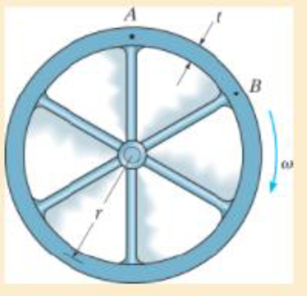
The rim on the flywheel has a thickness t, width b, and specific weight γ. If the flywheel is rotating at a constant rate of ω, determine the maximum moment developed in the rim. Assume that the spokes do not deform. Hint: Due to symmetry of the loading, the slope of the rim at each spoke is zero. Consider the radius to be sufficiently large so that the segment AB can be considered as a straight beam fixed at both ends and loaded with a uniform centrifugal force per unit length. Show that this force is w = btγω2r/g.
Want to see the full answer?
Check out a sample textbook solution
Chapter 12 Solutions
Mechanics of Materials
Additional Engineering Textbook Solutions
DESIGN OF MACHINERY
Automotive Technology: Principles, Diagnosis, And Service (6th Edition) (halderman Automotive Series)
Fundamentals of Aerodynamics
Applied Statics and Strength of Materials (6th Edition)
Degarmo's Materials And Processes In Manufacturing
Vector Mechanics For Engineers


- The L-shaped frame is made from two segments, each of length L and flexural stiffness EI. If it is subjected to the uniform distributed load, determine the vertical displacement of point B.arrow_forwardThe 50-mm-diameter shaft is supported by journal bearings at A and B. If the pulleys Cand D are subjected to the loadings shown, determine the absolute maximum bendingstress in the shaft.arrow_forwardThe cantilevered beam has a rectangular cross-sectional area A, a moment of inertia I, and a modulus of elasticity E. If a load P acts at point B as shown, determine the displacement at B in the direction of P, accounting for bending, axial force, and shear.arrow_forward
- Determine the resultant internal bending moment acting on the cross section at point C in the beam (express your answer in the box provided bellow in N.m without including the sign or its unit symbol). The load D=351 kg has a mass of and is being hoisted by the motor with constant velocity. -2 m 2 m 2 m 0.1 m 0.1 m -1m 1.5 m Darrow_forwardDetermine the internal normal force, shear force, and bending moment at points D and E of the bell crank that is pinned at A and supported by a short link BC.arrow_forwardDetermine the maximum allowable intensity w of the uniform distributed load that can be applied to the beam. Assume w passes through the centroid of the beam’s cross-sectional area, and the beam is simply supported at A and B. The allowable bending stress is sallow = 165 MPa.arrow_forward
- The beam shown has an overall length L of 6.9 metres. A uniform distributed load of 3.9 kN/m is applied as shown. If the distance x is 1.9 metres, determine the magnitude (in kNm) of the reaction moment at A. Note: Do NOT include the units in your answer.arrow_forwardSpecify the location of the single resultant load that can be used to replac A: 400 N/m www....mm 3m -3m- Barrow_forwardDetermine the reactions at the supports. The moment of inertia for each segment is shown in the figure. Assume the support at B is a roller. Take E=29(10^3)ksiarrow_forward
- Total upward force of 100 lbs is applied. Determine the forces at D and F on the ADF tong. Where is the region of maximum bending moment and shear load?arrow_forwardThe rigid bar AB and CD are supported by pins at A and D. the vertical rods are made of aluminum and bronze. Determine the vertical displacement of the point where the force P= 10 kips is applied. Neglect the weight of the members.arrow_forwardBar ABC has a rectangular cross section of 300 mm by 100 mm. The attached rod DB has a diameter of 20 mm. If both members are made of A-36 steel, determine the slope at A due to the loading. Consider only the effect of bending in ABC and axial force in DB.arrow_forward
 Elements Of ElectromagneticsMechanical EngineeringISBN:9780190698614Author:Sadiku, Matthew N. O.Publisher:Oxford University Press
 Mechanics of Materials (10th Edition)Mechanical EngineeringISBN:9780134319650Author:Russell C. HibbelerPublisher:PEARSON
 Thermodynamics: An Engineering ApproachMechanical EngineeringISBN:9781259822674Author:Yunus A. Cengel Dr., Michael A. BolesPublisher:McGraw-Hill Education
 Control Systems EngineeringMechanical EngineeringISBN:9781118170519Author:Norman S. NisePublisher:WILEY
 Mechanics of Materials (MindTap Course List)Mechanical EngineeringISBN:9781337093347Author:Barry J. Goodno, James M. GerePublisher:Cengage Learning
 Engineering Mechanics: StaticsMechanical EngineeringISBN:9781118807330Author:James L. Meriam, L. G. Kraige, J. N. BoltonPublisher:WILEY