
Mechanics of Materials, 7th Edition
7th Edition
ISBN: 9780073398235
Author: Ferdinand P. Beer, E. Russell Johnston Jr., John T. DeWolf, David F. Mazurek
Publisher: McGraw-Hill Education
expand_more
expand_more
format_list_bulleted
Concept explainers
Videos
Textbook Question
Chapter 11.9, Problem 77P
11.77 and 11.78 Using the information in Appendix D, compute the work of the loads as they are applied to the beam (a) if the load P is applied first, (b) if the couple M is applied first.
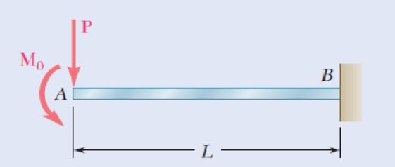
Fig. P11.77
Expert Solution & Answer
Want to see the full answer?
Check out a sample textbook solution
Students have asked these similar questions
Problem 1
A timber beam is to be designed to support a distributed load and up to two concentrated loads as
shown. One of the dimensions of its uniform rectangular cross section has been specified and the
other is to be determined so that the maximum normal stress in the beam will not exceed a given
allowable value oall. Write a computer program that can be used to calculate at given intervals
AL the shear, the bending moment, and the smallest acceptable value of the unknown dimension.
X2
X3
P2
A
В
L.
Apply this
and loading shown below, design the cross section of the beam, knowing that the grade of timber
used has an allowable normal stress of 12 MPa.
program to solve the following problem, using the intervals AL = 0.3 m: for the beam
2.5 kN
2.5 kN
6 kN/m
100 mm
D
h
3 m
0.6 m
0.6 m
A cable AB of span L and a simple beam A'B' of the same span are subjected to identical vertical loadings as shown. Show that the magnitude of the bending moment at a point C' in the beam is equal to the product T0h, where T0 is the magnitude of the horizontal component of the tension force in the cable and h is the vertical distance between point C and the chord joining the points of support A and B.
A 5 m beam is fixed at one end and pinned at other end. It is loaded a couple M at pinned end. If there is one unit rotation at the pinned connected end, EI = 1800 N.m^21. Which of the following gives the value of couple M in N.m at the pinned end? a. 1444b. 4414c. 4441d. 14142. Which of the following gives the value of vertical reaction at pinned end in N? a. 334b. 434c. 443d. 3443. Which of the following gives the value of moment at fixed end in N.m.? a. 334b. 434c. 443d. 344
Chapter 11 Solutions
Mechanics of Materials, 7th Edition
Ch. 11.3 - Determine the modulus of resilience for each of...Ch. 11.3 - Determine the modulus of resilience for each of...Ch. 11.3 - Determine the modulus of resilience for each of...Ch. 11.3 - Determine the modulus of resilience for each of...Ch. 11.3 - The stress-strain diagram shown has been drawn...Ch. 11.3 - The stress-strain diagram shown has been drawn...Ch. 11.3 - Prob. 7PCh. 11.3 - Prob. 8PCh. 11.3 - Using E = 29 106 psi, determine (a) the strain...Ch. 11.3 - Using E = 200 GPa, determine (a) the strain energy...
Ch. 11.3 - A 30-in. length of aluminum pipe of...Ch. 11.3 - A single 6-mm-diameter steel pin B is used to...Ch. 11.3 - Prob. 13PCh. 11.3 - Prob. 14PCh. 11.3 - The assembly ABC is made of a steel for which E =...Ch. 11.3 - Show by integration that the strain energy of the...Ch. 11.3 - Prob. 17PCh. 11.3 - Prob. 18PCh. 11.3 - Prob. 19PCh. 11.3 - 11.18 through 11.21 In the truss shown, all...Ch. 11.3 - Prob. 21PCh. 11.3 - Each member of the truss shown is made of aluminum...Ch. 11.3 - Each member of the truss shown is made of aluminum...Ch. 11.3 - 11.24 through 11.27 Taking into account only the...Ch. 11.3 - Prob. 25PCh. 11.3 - 11.24 through 11.27 Taking into account only the...Ch. 11.3 - 11.24 through 11.27 Taking into account only the...Ch. 11.3 - Prob. 28PCh. 11.3 - Prob. 29PCh. 11.3 - Prob. 30PCh. 11.3 - 11.30 and 11.31 Using E = 200 GPa, determine the...Ch. 11.3 - Assuming that the prismatic beam AB has a...Ch. 11.3 - Prob. 33PCh. 11.3 - The design specifications for the steel shaft AB...Ch. 11.3 - Show by integration that the strain energy in the...Ch. 11.3 - The state of stress shown occurs in a machine...Ch. 11.3 - Prob. 37PCh. 11.3 - The state of stress shown occurs in a machine...Ch. 11.3 - Prob. 39PCh. 11.3 - Prob. 40PCh. 11.3 - Prob. 41PCh. 11.5 - A 5-kg collar D moves along the uniform rod AB and...Ch. 11.5 - The 18-lb cylindrical block E has a horizontal...Ch. 11.5 - The cylindrical block E has a speed v0 =16 ft/s...Ch. 11.5 - Prob. 45PCh. 11.5 - Prob. 46PCh. 11.5 - The 48-kg collar G is released from rest in the...Ch. 11.5 - Prob. 48PCh. 11.5 - Prob. 49PCh. 11.5 - Prob. 50PCh. 11.5 - Prob. 51PCh. 11.5 - The 2-kg block D is dropped from the position...Ch. 11.5 - The 10-kg block D is dropped from a height h = 450...Ch. 11.5 - Prob. 54PCh. 11.5 - A 160-lb diver jumps from a height of 20 in. onto...Ch. 11.5 - Prob. 56PCh. 11.5 - A block of weight W is dropped from a height h...Ch. 11.5 - 11.58 and 11.59 Using the method of work and...Ch. 11.5 - 11.58 and 11.59 Using the method of work and...Ch. 11.5 - 11.60 and 11.61 Using the method of work and...Ch. 11.5 - 11.60 and 11.61 Using the method of work and...Ch. 11.5 - 11.62 and 11.63 Using the method of work and...Ch. 11.5 - 11.62 and 11.63 Using the method of work and...Ch. 11.5 - Using the method of work and energy, determine the...Ch. 11.5 - Using the method of work and energy, determine the...Ch. 11.5 - The 20-mm diameter steel rod BC is attached to the...Ch. 11.5 - Torques of the same magnitude T are applied to the...Ch. 11.5 - Prob. 68PCh. 11.5 - The 20-mm-diameter steel rod CD is welded to the...Ch. 11.5 - The thin-walled hollow cylindrical member AB has a...Ch. 11.5 - 11.71 and 11.72 Each member of the truss shown has...Ch. 11.5 - 11.71 and 11.72 Each member of the truss shown has...Ch. 11.5 - Each member of the truss shown is made of steel...Ch. 11.5 - Each member of the truss shown is made of steel....Ch. 11.5 - Each member of the truss shown is made of steel...Ch. 11.5 - The steel rod BC has a 24-mm diameter and the...Ch. 11.9 - 11.77 and 11.78 Using the information in Appendix...Ch. 11.9 - 11.77 and 11.78 Using the information in Appendix...Ch. 11.9 - 11.79 through 11.82 For the beam and loading...Ch. 11.9 - 11.79 through 11.82 For the beam and loading...Ch. 11.9 - 11.79 through 11.82 For the beam and loading...Ch. 11.9 - 11.79 through 11.82 For the beam and loading...Ch. 11.9 - 11.83 through 11.85 For the prismatic beam shown,...Ch. 11.9 - 11.83 through 11.85 For the prismatic beam shown,...Ch. 11.9 - 11.83 through 11.85 For the prismatic beam shown,...Ch. 11.9 - 11.86 through 11.88 For the prismatic beam shown,...Ch. 11.9 - 11.86 through 11.88 For the prismatic beam shown,...Ch. 11.9 - 11.86 through 11.88 For the prismatic beam shown,...Ch. 11.9 - For the prismatic beam shown, determine the slope...Ch. 11.9 - For the prismatic beam shown, determine the slope...Ch. 11.9 - For the beam and loading shown, determine the...Ch. 11.9 - For the beam and loading shown, determine the...Ch. 11.9 - 11.93 and 11.94 For the beam and loading shown,...Ch. 11.9 - 11.93 and 11.94 For the beam and loading shown,...Ch. 11.9 - For the beam and loading shown, determine the...Ch. 11.9 - For the beam and loading shown, determine the...Ch. 11.9 - Prob. 97PCh. 11.9 - For the beam and loading shown, determine the...Ch. 11.9 - 11.99 and 11.100 For the truss and loading shown,...Ch. 11.9 - 11.99 and 11.100 For the truss and loading shown,...Ch. 11.9 - 11.101 and 11.102 Each member of the truss shown...Ch. 11.9 - 11.101 and 11.102 Each member of the truss shown...Ch. 11.9 - 11.103 and 11.104 Each member of the truss shown...Ch. 11.9 - 11.103 and 11 104 Each member of the truss shown...Ch. 11.9 - A uniform rod of flexural rigidity EI is bent and...Ch. 11.9 - For the uniform rod and loading shown and using...Ch. 11.9 - For the beam and loading shown and using...Ch. 11.9 - Two rods AB and BC of the same flexural rigidity...Ch. 11.9 - Three rods, each of the same flexural rigidity EI,...Ch. 11.9 - Three rods, each of the same flexural rigidity EI,...Ch. 11.9 - 11.111 through 11.115 Determine the reaction at...Ch. 11.9 - 11.111 through 11.115 Determine the reaction at...Ch. 11.9 - 11.111 through 11.115 Determine the reaction at...Ch. 11.9 - 11.111 through 11.115 Determine the reaction at...Ch. 11.9 - 11.111 through 11.115 Determine the reaction at...Ch. 11.9 - For the uniform beam and loading shown, determine...Ch. 11.9 - 11.117 through 11.120 Three members of the same...Ch. 11.9 - 11.117 through 11.120 Three members of the same...Ch. 11.9 - 11.117 through 11.120 Three members of the same...Ch. 11.9 - 11.117 through 11.120 Three members of the same...Ch. 11.9 - 11.121 and 11.122 Knowing that the eight members...Ch. 11.9 - 11.121 and 11.122 Knowing that the eight members...Ch. 11 - Rod AB is made of a steel for which the yield...Ch. 11 - Each member of the truss shown is made of steel...Ch. 11 - The ship at A has just started to drill for oil on...Ch. 11 - Collar D is released from rest in the position...Ch. 11 - Each member of the truss shown is made of steel...Ch. 11 - A block of weight W is placed in contact with a...Ch. 11 - Two solid steel shafts are connected by the gears...Ch. 11 - A 160-lb diver jumps from a height of 20 in. onto...Ch. 11 - For the prismatic beam shown, determine the slope...Ch. 11 - A disk of radius a has been welded to end B of the...Ch. 11 - A uniform rod of flexural rigidity EI is bent and...Ch. 11 - The steel bar ABC has a square cross section of...
Knowledge Booster


Learn more about
Need a deep-dive on the concept behind this application? Look no further. Learn more about this topic, mechanical-engineering and related others by exploring similar questions and additional content below.Similar questions
- 9. Draw the shearing-force and bending-moment diagrams for the following beams: A cantilever of length 20 m carrying a load of 10 kN at a distance of 15 m from the supported end. A cantilever of length 20 m carrying a load of 10 KN uniformly distributed over the inner 15 m of its length. A cantilever of length 12 m carrying a load of 8 kN, applied 5 m from the supported end, and a load of 2kN/m over its whole length. A beam, 20 m span, simply-supported at each end and carrying a vertical load of 20 kN at a distance 5 m from one support. A beam, 16 m span, simply-supported at each end and carrying a vertical load of 2.5 kN at a distance of 4 m from one support and the beam itself weighing 500 N per i. ii. iii. iv. V. metre.arrow_forwardDraw the shearing-force and bending-moment diagrams for the following beams: A cantilever of length 20 m carrying a load of 10 kN at a distance of 15 m from the supported end. A cantilever of length 20 m carrying a load of 10 kN uniformly distributed over the inner 15 m of its length. A cantilever of length 12 m carrying a load of 8 kN, applied 5 m from the supported end, and a load of 2kN/m over its whole length.arrow_forwardNote: In the second method, the uniformly distributed load between A and C will cause anticlockwise moment about C, while the load between C and B will cause clockwise moment. But for the sake of simplicity, we have taken the entire load from A to B (equal to 0.6 × 5) acting at its centre (i.e. 2.5 m from A or 2.5 - x) from C. EXERCISE 12.1 1. A simply supported beam AB of span 4 m is carrying a point loads of 5, 2 and 3 kN at 1, 2 and 3 m respectively from the support A. Calculate the reactions at the supports A and B. [Ans. 5.5 kN and 4.5 kN] 2. A simply supported beam of span 6 m is carrying a uniformly distributed load of 2 kN/m over a length of 3 m from the right end B. Calculate the support reactions. [Ans. R = 1.5 kN, R, = 4.5 kN] 3. A simply supported beam AB of span 6 m is loaded as shown in Fig. 12.14. 2 kN 5 kN 2 kN/m 2 kN/m +1.5 m→ A В E 3 m D +1.5 m- 6 m Fig. 12.14. Determine the reactions at A and B. [Ans. 6.875 kN, 9.125 kN] 226 I A Textbook of Engineering Mechanics 4. A…arrow_forward
- Task 1 Determine the reactions at supports (A) and (B) which carry the conveyer beam to sustain a concentrated load of 3 kN and a uniformly distributed load of 6 kN/m as shown in Fig. (1). 1m 6 kN/m 1 m 3 kN Fig. (1) 2m Barrow_forwardExample 11.8: A three hinged arch of span 16 m has its abutments A and B at depth of 4 m and 8 m helow the crown C. The arch carries the load system as shown in Fig. 11.15. Determine the horizontal thrust and vertical reactions at supports. 100 kN 200 kN W = 30 kN/m L3 m 4 m13m 4 m H AV 8 m 6 m B Н ---- 10 m -arrow_forward(b) The gudgeon pin is used to connect the piston and the connecting rod. Show from first principles that the maximum bending moment acting on the gudgeon pin is given by: PL M = 8 where P is the maximum gas load and L is the length of the pinarrow_forward
- 7.9 Draw the shearing-force and bending-moment diagrams for the following beams: A cantilever of length 20 m carrying a load of 10 kN at a distance of 15 m from the supported end. A cantilever of length 20 m carrying a load of 10 kN uniformly distributed over the inner 15 m of its length A cantilever of length 12 m carrying a load of 8 kN, applied 5 m from the supported end, and a load of 2kNlm over its whole length A beam, 20 m span, simply-supported at each end and carrying a vertical load of 20 kN at a distance 5 m from one support. A beam, 16 m span, simply-supported at each end and carrying a vertical load of 2.5 kN at a distance of 4 m from one support and the beam itself weighing 500 N per metre.arrow_forwardProblem 2. (a) Draw the moment diagram for the beam. (b) Observing the direction of load and sign of the moment diagram, and knowledge of the boundary conditions, sketch the elastic curve, that is, the vertical deflection of the axial line thru the centroid of the beam section, (c) Using integration, determine the equation of the elastic curve for the beam using the x coordinate that is valid for 0 < x < L/2. (d) Specify the slope at A and the beam's maximum deflection. El is constant. For parts (a) and (b), model only one-half of the beam, from x=0 to x=L/2, and use the symmetry dv boundary condition, slope = 0, at the vertical line of symmetry at x=L/2. dx X NA Barrow_forwardP.7.13 Three identical bars of length L are hung in a vertical position as shown in Fig. P.7.13. A rigid, weightless beam is attached to their lower ends and this in turn carries a load P. Calculate the load in each bar. Ans. P=Pl12, P2=P13, P3=7P/12. 1 2 P FIGURE P.7.13 a al2arrow_forward
- Problem 7. The 30-mm diameter shaft is subjected to the vertical and horizontal loadings of two pulleys as shown. It is supported on two journal bearings at A and B which offer no resistance to axial loading. Furthermore, the coupling to the motor at C can be assumed not to offer any support to the shaft. The shaft is subjected to both Mz and My internal bending moment components. (a) Draw a bending moment diagram for each component. (b) Since all axes through the circle's center for circular shaft are principal axis, then the resultant M = √M²+ M² can be used to determine the y maximum bending stress. Determine the location and magnitude of maximum normal stress due to bending developed in the shaft. X 150 N 1 m 2 150 N 1 m E 60 mm 1 m 100 mm 1 m 400 N 400 Narrow_forward2. A cover-plate beam is made up of an I-Beam section with 300 mm x 12 mm plates attached to the top and bottom flanges and is fastened by two rows of 20 mm rivets. The beam is simply supported over a span of 6m and carries a uniformly distributed load of 270 kN/m including its own weight. a. Determine the distance from the centroid of the cover plate to the neutral axis of the built-up section. b. Determine the moment of inertia of the built-up section about its neutral axis. c. Determine the maximum flexural stress of the built-up section. 200 mm 30 mm 310 mm 30 mm 30 mmarrow_forwardPROBLEM 10.21 10.21 The uniform brass bar AB has a rectangular cross section and is supported by pins and brackets as shown. Each end of the bar can rotate freely about a horizontal axis through the pin, but rotation about a vertical axis is prevented by the brackets. (a) Determine the ratio bld for which the factor of safety is the same about the horizontal and vertical axes. (b) Determine the factor of safety if P = 8 L = 2m, d = 38 mm, and E = 105 GPa. B kN,arrow_forward
arrow_back_ios
SEE MORE QUESTIONS
arrow_forward_ios
Recommended textbooks for you
 Elements Of ElectromagneticsMechanical EngineeringISBN:9780190698614Author:Sadiku, Matthew N. O.Publisher:Oxford University Press
 Mechanics of Materials (10th Edition)Mechanical EngineeringISBN:9780134319650Author:Russell C. HibbelerPublisher:PEARSON
 Thermodynamics: An Engineering ApproachMechanical EngineeringISBN:9781259822674Author:Yunus A. Cengel Dr., Michael A. BolesPublisher:McGraw-Hill Education
 Control Systems EngineeringMechanical EngineeringISBN:9781118170519Author:Norman S. NisePublisher:WILEY
 Mechanics of Materials (MindTap Course List)Mechanical EngineeringISBN:9781337093347Author:Barry J. Goodno, James M. GerePublisher:Cengage Learning
 Engineering Mechanics: StaticsMechanical EngineeringISBN:9781118807330Author:James L. Meriam, L. G. Kraige, J. N. BoltonPublisher:WILEY
Elements Of Electromagnetics
Mechanical Engineering
ISBN:9780190698614
Author:Sadiku, Matthew N. O.
Publisher:Oxford University Press
Mechanics of Materials (10th Edition)
Mechanical Engineering
ISBN:9780134319650
Author:Russell C. Hibbeler
Publisher:PEARSON
Thermodynamics: An Engineering Approach
Mechanical Engineering
ISBN:9781259822674
Author:Yunus A. Cengel Dr., Michael A. Boles
Publisher:McGraw-Hill Education
Control Systems Engineering
Mechanical Engineering
ISBN:9781118170519
Author:Norman S. Nise
Publisher:WILEY
Mechanics of Materials (MindTap Course List)
Mechanical Engineering
ISBN:9781337093347
Author:Barry J. Goodno, James M. Gere
Publisher:Cengage Learning
Engineering Mechanics: Statics
Mechanical Engineering
ISBN:9781118807330
Author:James L. Meriam, L. G. Kraige, J. N. Bolton
Publisher:WILEY
EVERYTHING on Axial Loading Normal Stress in 10 MINUTES - Mechanics of Materials; Author: Less Boring Lectures;https://www.youtube.com/watch?v=jQ-fNqZWrNg;License: Standard YouTube License, CC-BY