
Fundamentals of Electric Circuits
6th Edition
ISBN: 9780078028229
Author: Charles K Alexander, Matthew Sadiku
Publisher: McGraw-Hill Education
expand_more
expand_more
format_list_bulleted
Concept explainers
Videos
Textbook Question
Chapter 11, Problem 21P
Assuming that the load impedance is to be purely resistive, what load should be connected to terminals a-b of the circuits in Fig. 11.52 so that the maximum power is transferred to the load?
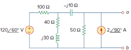
Figure 11.52
Expert Solution & Answer
Want to see the full answer?
Check out a sample textbook solution
Students have asked these similar questions
A three phase converter has a rating of 500 kW when operating at unity power factor. Neglecting any change in efficiency , what would be its rating when operating at a power factor of 0.8
A resistance of 20 ohm and a coil of inductance 31.8 mH and negligible resistance are connected in
parallel across 230V, 50 Hz supply. Find the
A) Line Current
B) Power Factor
C) Power consumed by the circuit
11.15 In the circuit of Fig. 11.46, find the value of Z, that
will absorb the maximum power and the value of the
maximum power.
120/0° V
192
wwwww
--/12
V./19
V₂
2V₂
ZL
Chapter 11 Solutions
Fundamentals of Electric Circuits
Ch. 11.2 - Calculate the instantaneous power and average...Ch. 11.2 - A current A flows through an impedance Find the...Ch. 11.2 - In the circuit of Fig. 11.4, calculate the average...Ch. 11.2 - Calculate the average power absorbed by each of...Ch. 11.3 - For the circuit shown in Fig. 11.10, find the load...Ch. 11.3 - In Fig. 11.12, the resistor RL is adjusted until...Ch. 11.4 - Find the rms value of the current waveform of Fig....Ch. 11.4 - Find the rms value of the full-wave rectified sine...Ch. 11.5 - Prob. 9PPCh. 11.5 - Prob. 10PP
Ch. 11.6 - For a load, Determine: (a) the complex and...Ch. 11.6 - A sinusoidal source supplies 100 kVAR reactive...Ch. 11.7 - In the circuit in Fig. 11.25, the 60- resistor...Ch. 11.7 - Two loads connected in parallel are respectively 3...Ch. 11.8 - Find the value of parallel capacitance needed to...Ch. 11.9 - For the circuit in Fig. 11.33, find the wattmeter...Ch. 11.9 - The monthly reading of a paper mills meter is as...Ch. 11.9 - An 500-kW induction furnace at 0.88 power factor...Ch. 11 - The average power absorbed by an inductor is zero,...Ch. 11 - The Thevenin impedance of a network seen from the...Ch. 11 - The amplitude of the voltage available in the...Ch. 11 - If the load impedance is 20 j20, the power factor...Ch. 11 - A quantity that contains all the power information...Ch. 11 - Reactive power is measured in: (a) watts (b) VA...Ch. 11 - In the power triangle shown in Fig. 11.34(a), the...Ch. 11 - For the power triangle in Fig. 11.34(b), the...Ch. 11 - A source is connected to three loads Z1, Z2, and...Ch. 11 - The instrument for measuring average power is the:...Ch. 11 - If v(t) = 160 cos 50t V and i(t) = 33 sin (50t ...Ch. 11 - Given the circuit in Fig. 11.35, find the average...Ch. 11 - A load consists of a 60- resistor in parallel with...Ch. 11 - Using Fig. 11.36, design a problem to help other...Ch. 11 - ssuming that vs = 8 cos(2t 40) V in the circuit...Ch. 11 - For the circuit in Fig. 11.38, is = 6 cos 103t A....Ch. 11 - Given the circuit of Fig. 11.39, find the average...Ch. 11 - In the circuit of Fig. 11.40, determine the...Ch. 11 - For the op amp circuit in Fig. 11.41, Find the...Ch. 11 - In the op amp circuit in Fig. 11.42, find the...Ch. 11 - For the network in Fig. 11.43, assume that the...Ch. 11 - For the circuit shown in Fig. 11.44, determine the...Ch. 11 - The Thevenin impedance of a source is ZTh = 120 +...Ch. 11 - Using Fig. 11.45, design a problem to help other...Ch. 11 - In the circuit of Fig. 11.46, find the value of ZL...Ch. 11 - For the circuit in Fig. 11.47, find the value of...Ch. 11 - Calculate the value of ZL in the circuit of Fig....Ch. 11 - Find the value of ZL in the circuit of Fig. 11.49...Ch. 11 - The variable resistor R in the circuit of Fig....Ch. 11 - The load resistance RL in Fig. 11.51 is adjusted...Ch. 11 - Assuming that the load impedance is to be purely...Ch. 11 - Find the rms value of the offset sine wave shown...Ch. 11 - Using Fig. 11.54, design a problem to help other...Ch. 11 - Determine the rms value of the waveform in Fig....Ch. 11 - Find the rms value of the signal shown in Fig....Ch. 11 - Find the effective value of the voltage waveform...Ch. 11 - Calculate the rms value of the current waveform of...Ch. 11 - Find the rms value of the voltage waveform of Fig,...Ch. 11 - Calculate the effective value of the current...Ch. 11 - Compute the rms value of the waveform depicted in...Ch. 11 - Find the rms value of the signal shown in Fig....Ch. 11 - Obtain the rms value of the current waveform shown...Ch. 11 - Determine the rms value for the waveform in Fig....Ch. 11 - Find the effective value f(t) defined in Fig....Ch. 11 - One cycle of a periodic voltage waveform is...Ch. 11 - Calculate the rms value for each of the following...Ch. 11 - Design a problem to help other students better...Ch. 11 - For the power system in Fig. 11.67, find: (a) the...Ch. 11 - An ac motor with impedance ZL = 2 + j 1.2 is...Ch. 11 - Design a problem to help other students better...Ch. 11 - Obtain the power factor for each of the circuits...Ch. 11 - A 110-V rms, 60-Hz source is applied to a load...Ch. 11 - Design a problem to help other students understand...Ch. 11 - Find the complex power delivered by vs to the...Ch. 11 - The voltage across a load and the current through...Ch. 11 - For the following voltage and current phasors,...Ch. 11 - For each of the following cases, find the complex...Ch. 11 - Determine the complex power for the following...Ch. 11 - Find the complex power for the following cases:...Ch. 11 - Obtain the overall impedance for the following...Ch. 11 - For the entire circuit in Fig. 11.70, calculate:...Ch. 11 - In the circuit of Fig. 11.71, device A receives 2...Ch. 11 - In the circuit of the Fig. 11.72, load A receives...Ch. 11 - For the network in Fig. 11.73, find the complex...Ch. 11 - Using Fig. 11.74, design a problem to help other...Ch. 11 - Obtain the complex power delivered by the source...Ch. 11 - For the circuit in Fig. 11.76, find the average,...Ch. 11 - Obtain the complex power delivered to the 10-k...Ch. 11 - Calculate the reactive power in the inductor and...Ch. 11 - For the circuit in Fig. 11.79, find Vo and the...Ch. 11 - Given the circuit in Fig. 11.80, find Io and the...Ch. 11 - For the circuit in Fig. 11.81, find Vs.Ch. 11 - Find Io in the circuit of Fig. 11.82. Figure 11.82Ch. 11 - Determine Is in the circuit of Fig. 11.83, if the...Ch. 11 - In the op amp circuit of Fig. 11.84, vs = 4 cos...Ch. 11 - Obtain the average power absorbed by the 10-...Ch. 11 - For the op amp circuit in Fig. 11.86, calculate:...Ch. 11 - Compute the complex power supplied by the current...Ch. 11 - Refer to the circuit shown in Fig. 11.88. (a) What...Ch. 11 - Design a problem to help other students better...Ch. 11 - Three loads are connected in parallel to a rms...Ch. 11 - Two loads connected in parallel draw a total of...Ch. 11 - A 240-V rms 60-Hz supply serves a load that is 10...Ch. 11 - A 120-V rms 60-Hz source supplies two loads...Ch. 11 - Consider the power system shown in Fig. 11.90....Ch. 11 - Obtain the wattmeter reading of the circuit in...Ch. 11 - What is the reading of the wattmeter in the...Ch. 11 - Find the wattmeter reading of the circuit shown in...Ch. 11 - Determine the wattmeter reading of the circuit in...Ch. 11 - The circuit of Fig. 11.95 portrays a wattmeter...Ch. 11 - Design a problem to help other students better...Ch. 11 - A 240-V rms 60-Hz source supplies a parallel...Ch. 11 - Oscilloscope measurements indicate that the peak...Ch. 11 - A consumer has an annual consumption of 1200 MWh...Ch. 11 - A regular household system of a single-phase...Ch. 11 - A transmitter delivers maximum power to an antenna...Ch. 11 - In a TV transmitter, a series circuit has an...Ch. 11 - A certain electronic circuit is connected to a...Ch. 11 - An industrial heater has a nameplate that reads:...Ch. 11 - A 2000-kW turbine-generator of 0.85 power factor...Ch. 11 - The nameplate of an electric motor has the...Ch. 11 - As shown in Fig. 11.97, a 550-V feeder line...Ch. 11 - A factory has the following four major loads: A...Ch. 11 - A 1-MVA substation operates at full load at 0.7...Ch. 11 - Prob. 95CPCh. 11 - A power amplifier has an output impedance of 40 +...Ch. 11 - A power transmission system is modeled as shown in...
Additional Engineering Textbook Solutions
Find more solutions based on key concepts
Explain the main function of each of the following major components of a PLC: a. Processor module (CPU) b. I/O ...
Programmable Logic Controllers
The current source in the circuit shown generates the current pulse
Find (a) v (0); (b) the instant of time gr...
Electric Circuits. (11th Edition)
Does the severity of an electric shock increase ordecrease with eh of the following changes? a. A decrease in t...
Electric Motors and Control Systems
Electric power systems provide energy in a variety of commercial and industrial settings. Make a list of system...
Principles and Applications of Electrical Engineering
A constant voltage of 10V is applied to a 50H inductance, as shown in Figure P3.51 Figure P3 51 The current in ...
Electrical Engineering: Principles & Applications (7th Edition)
Three point charges of equal magnitude q, that will yield a zero net electric field at the origin.
Engineering Electromagnetics
Knowledge Booster


Learn more about
Need a deep-dive on the concept behind this application? Look no further. Learn more about this topic, electrical-engineering and related others by exploring similar questions and additional content below.Similar questions
- A 5KVA ideal transformer supplied with 120V RMS and connected to a 1kQ load draws 2A RMS of current on the secondary. What load must be connected in order to draw full power? 1kQ 2.5kQ 8000 3.50arrow_forwardb) A 250V is used to supply a 20kW load at 50HZ with leading power factor of 0.75. Determine the following : ii. State whether this load is generating or consuming reactive power.arrow_forward11. A series circuit composed of a resistance of 24 ohms, an inductance of 0.09 henry and a capacitance of 8 microfarad, is connected to a 120-volt 50-Hz supply. Calculate the power factor of the circuit 0.125 leading O 0.065 leading O 0.125 lagging O 0.065 laggingarrow_forward
- A 5-ohm resistor is connected in series with a 25 micro-farad capacitor. A source voltage of 158 volts, 50 Hz supplies the combination. Determine the following: d. Real power supplied by the source e. Reactive power supplied by the source f. Apparent power of the circuit g. Power factor of the entire circuitarrow_forwardA capacitor drawing 4 kvar is placed in parallel with the electro-magnet that draws 3 kW of active power and 4 kvar of reactive power.. a. Calculate the new value of apparent power b. What is the new value of reactive power? c. What is the value of active power? d. What is the new power factor?arrow_forwardA 96 kVA load operates at 0.79 lagging power factor when connected to a 230 V, 60Hz AC source. The power factor is to be improved to 0.93 lagging. The power factor is to be corrected by a capacitor bank. However, the capacitors are loosely connected and take 34 kW when connected to a 230V, 60Hz AC source. What is the kVAR rating of the capacitor bank?arrow_forward
- A SINGLE-PHASE STEP-DOWN TRANSFORMER 1320/220 VAC 60HZ. IT SUPPLIES A LOAD 1 FORMED BY A 18 Ω RESISTOR IN SERIES WITH A 60 mH COIL. IN PARALLEL WITH LOAD 1 IS A LOAD 2 CONSISTING OF A RESISTIVE HEATER WHICH CONSUMES 700 WDETERMINE:A) THE VALUE OF THE REAL POWER CONSUMED ONLY BY LOAD 1B) THE VALUE OF THE TOTAL POWER FACTORC) THE VALUE OF THE MAGNITUDE OF THE CURRENT IN THE PRIMARY OF THE TRANSFORMER.D) VALUE OF THE CAPACITOR IN μF TO BE CONNECTED IN PARALLEL TO THE TWO LOADS TO HAVE A POWER FACTOR EQUAL TO 1.arrow_forwardYour aunt living in the USA sent an appliance that has impedance equal to 10 + j3 2 at 60 Hz. She instructed you to purchase a 220 V to 110 V transformer to step down the voltage since the appliance is rated 110 V. The cord that you used to connect the 220 V side of the transformer to the convenience outlet has a total impedance of 1 + j0.5 Q. You measured the voltage at the outlet and the value is 220 Vrms. The equivalent circuit is shown below: j0.5 Ω 1Ω mm N220 V rms 10 + j3 V₁ Ω 220 V 110 V Solve for the voltage across the appliance and the current through it by either A. Referring the appliance to the transformer primary, OR B. Referring the source and cord impedance to the transformer secondary. Assign the convenience outlet voltage as the reference phasor, i.e. at 0°. Choose only one method above. After choosing, 1. Draw the circuit that would solve for V₁ and I. Compute all referred values and label all components. 2. Solve for V₁ and I₁. S + Iarrow_forwardA 1500 kvA, 3Φ star-connected alternator, 50 Hz,2300 V alternator has a resistance between each pair of terminals as measured by direct currents is 0.16 ohm. Assume that the effective resistance is 1.5 times the ohmic value. A field current of 70 A produces a short-circuit current equal to full load current of 376 A in each line. The same field current produces an emf of 700 V on open circuit. Determine the synchronous reactance of the machine and its full load voltage regulation at 0.8 power factor lagging. [Ans. VR = 22.8 %]arrow_forward
- Your aunt living in the USA sent an appliance that has impedance equal to 10 + j3 2 at 60 Hz. She instructed you to purchase a 220 V to 110 V transformer to step down the voltage since the appliance is rated 110 V. The cord that you used to connect the 220 V side of the transformer to the convenience outlet has a total impedance of 1 + j0.5 Q. You measured the voltage at the outlet and the value is 220 Vrms. The equivalent circuit is shown below: 1 Ω m T 220 V rms 10+ j3 V Ω 220 V : 110 V Solve for the voltage across the appliance and the current through it by either A. Referring the appliance to the transformer primary, OR B. Referring the source and cord impedance to the transformer secondary. Assign the convenience outlet voltage as the reference phasor, i.e. at 0°. Choose only one method above. After choosing, j0.5 Q +arrow_forwardYour aunt living in the USA sent an appliance that has impedance equal to 10 + j3 2 at 60 Hz. She instructed you to purchase a 220 V to 110 V transformer to step down the voltage since the appliance is rated 110 V. The cord that you used to connect the 220 V side of the transformer to the convenience outlet has a total impedance of 1 + j0.5 Q. You measured the voltage at the outlet and the value is 220 Vrms. The equivalent circuit is shown below: j0.5 Q 19 ww + (N) 220 V rms 10+ j3 VL Ω 220 V : 110 V Solve for the voltage across the appliance and the current through it by either A. Referring the appliance to the transformer primary, OR B. Referring the source and cord impedance to the transformer secondary. Assign the convenience outlet voltage as the reference phasor, i.e. at 0°. Choose only one method above. After choosing, 1. Draw the circuit that would solve for V₁ and T. Compute all referred values and label all components. 2. Solve for V and I.arrow_forwardYour aunt living in the USA sent an appliance that has impedance equal to 10+ j3 2 at 60 Hz. She instructed you to purchase a 220 V to 110 V transformer to step down the voltage since the appliance is rated 110 V. The cord that you used to connect the 220 V side of the transformer to the convenience outlet has a total impedance of 1 + j0.5 Q. You measured the voltage at the outlet and the value is 220 Vrms. The equivalent circuit is shown below: 1Ω mm ĪT + 10+j3 VL 220 V rms Ω 220 V : 110 V Solve for the voltage across the appliance and the current through it by either A. Referring the appliance to the transformer primary, OR B. Referring the source and cord impedance to the transformer secondary. Assign the convenience outlet voltage as the reference phasor, i.e. at 0°. Choose only one method above. After choosing, 1. Draw the circuit that would solve for V₁ and T. Compute all referred values and label all components. 2. Solve for V and I. j0.5 Q +arrow_forward
arrow_back_ios
SEE MORE QUESTIONS
arrow_forward_ios
Recommended textbooks for you
 Introductory Circuit Analysis (13th Edition)Electrical EngineeringISBN:9780133923605Author:Robert L. BoylestadPublisher:PEARSON
 Delmar's Standard Textbook Of ElectricityElectrical EngineeringISBN:9781337900348Author:Stephen L. HermanPublisher:Cengage Learning
 Programmable Logic ControllersElectrical EngineeringISBN:9780073373843Author:Frank D. PetruzellaPublisher:McGraw-Hill Education
 Fundamentals of Electric CircuitsElectrical EngineeringISBN:9780078028229Author:Charles K Alexander, Matthew SadikuPublisher:McGraw-Hill Education
 Electric Circuits. (11th Edition)Electrical EngineeringISBN:9780134746968Author:James W. Nilsson, Susan RiedelPublisher:PEARSON
 Engineering ElectromagneticsElectrical EngineeringISBN:9780078028151Author:Hayt, William H. (william Hart), Jr, BUCK, John A.Publisher:Mcgraw-hill Education,
Introductory Circuit Analysis (13th Edition)
Electrical Engineering
ISBN:9780133923605
Author:Robert L. Boylestad
Publisher:PEARSON
Delmar's Standard Textbook Of Electricity
Electrical Engineering
ISBN:9781337900348
Author:Stephen L. Herman
Publisher:Cengage Learning
Programmable Logic Controllers
Electrical Engineering
ISBN:9780073373843
Author:Frank D. Petruzella
Publisher:McGraw-Hill Education
Fundamentals of Electric Circuits
Electrical Engineering
ISBN:9780078028229
Author:Charles K Alexander, Matthew Sadiku
Publisher:McGraw-Hill Education
Electric Circuits. (11th Edition)
Electrical Engineering
ISBN:9780134746968
Author:James W. Nilsson, Susan Riedel
Publisher:PEARSON
Engineering Electromagnetics
Electrical Engineering
ISBN:9780078028151
Author:Hayt, William H. (william Hart), Jr, BUCK, John A.
Publisher:Mcgraw-hill Education,
How Electric Motors Work - 3 phase AC induction motors ac motor; Author: The Engineering Mindset;https://www.youtube.com/watch?v=59HBoIXzX_c;License: Standard Youtube License